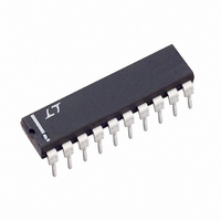
LT1161CN Linear Technology, LT1161CN Datasheet - Page 2

LT1161CN
Manufacturer Part Number
LT1161CN
Description
IC MOSFET DRIVER N-CH QUAD 20DIP
Manufacturer
Linear Technology
Datasheet
1.LT1161CSWPBF.pdf
(12 pages)
Specifications of LT1161CN
Configuration
High-Side
Input Type
Non-Inverting
Delay Time
220µs
Number Of Configurations
4
Number Of Outputs
4
Voltage - Supply
8 V ~ 48 V
Operating Temperature
0°C ~ 70°C
Mounting Type
Through Hole
Package / Case
20-DIP (0.300", 7.62mm)
Lead Free Status / RoHS Status
Contains lead / RoHS non-compliant
Current - Peak
-
High Side Voltage - Max (bootstrap)
-
Available stocks
Company
Part Number
Manufacturer
Quantity
Price
Part Number:
LT1161CN
Manufacturer:
LT/凌特
Quantity:
20 000
Part Number:
LT1161CN#PBF
Manufacturer:
LINEAR/凌特
Quantity:
20 000
ABSOLUTE
LT1161
Supply Voltages (Pins 11, 20) ................... – 15V to 60V
Input Voltages (Pins 3, 5, 7, 9) ...... (GND – 0.3V) to 15V
Gate Voltages (Pins 12, 14, 16, 18) ........................ 75V
Sense Voltages (Pins 13, 15, 17, 19) ................. V
Current (Any Pin) .................................................. 50mA
Operating Temperature Range
Junction Temperature Range (Note 1)
Storage Temperature Range ................. – 65°C to 150°C
Lead Temperature (Soldering, 10 sec).................. 300°C
temperature range, otherwise specifications are at T
SYMBOL
I
∆I
V
V
I
C
V
V
I
V
I
V
t
t
t
ELECTRICAL CHARACTERISTICS
Note 1: Stresses beyond those listed under Absolute Maximum Ratings
may cause permanent damage to the device. Exposure to any Absolute
Maximum Rating condition for extended periods may affect device
reliability and lifetime.
2
S
IN
T
SEN
ON
OFF
OFF(CL)
INH
INL
IN
T(TH)
T(CL)
SEN
GATE
S(ON)
LT1161C ............................................... 0°C to 70°C
LT1161I ............................................ – 40°C to 85°C
LT1161C .............................................. 0°C to 125°C
LT1161I ......................................... – 40°C to 150°C
– V
+
PARAMETER
Supply Current
Delta Supply Current (ON State)
Input High Voltage
Input Low Voltage
Input Current
Input Capacitance
Timer Threshold Voltage
Timer Clamp Voltage
Timer Charge Current
Drain Sense Threshold Voltage
Temperature Coefficient
Drain Sense Input Current
Gate Voltage Above Supply
Turn-ON Time
Turn-OFF Time
Current Limit Turn-OFF Time
W
MAXIMUM
W W
RATINGS
CONDITIONS
All Channels OFF (Note 2)
Measure Increase in I
V
V
V
V
V
V
V
V
V
V
V
V
V
IN
IN
IN
IN
IN
+
+
+
+
+
+
+
+
= 48V, V
= 8V
= 12V
= 24V
= 48V
= 24V, V
= 24V, V
= 24V, (V
= 2V
= 5V
= 2V, Adjust V
= 0.8V
= V
T
= 2V
U
A
SEN
GATE
GATE
+
= 25°C. V
– V
= 65mV
> 32V, C
< 2V, C
+
SENSE
T
The
±5V
S
per Channel
●
) → 0.1V, C
GATE
+
GATE
denotes specifications which apply over the full operating
= 12V to 48V each channel, unless otherwise noted.
= 1000pF
= 1000pF
PACKAGE/ORDER
Note 2: Both V
ground pins (1, 10) must be connected together.
Consult LTC Marketing for parts specified with wider operating temperature ranges.
Order Options Tape and Reel: Add #TR
Lead Free: Add #PBF Lead Free Tape and Reel: Add #TRPBF
Lead Free Part Marking:
GATE
20-LEAD PLASTIC DIP
TIMER 2
TIMER 3
TIMER 4
INPUT 1
INPUT 2
INPUT 3
INPUT 4
TIMER1
= 1000pF
N PACKAGE
GND
GND
+
10
1
2
3
4
5
6
7
8
9
pins (11, 20) must be connected together and both
θ
θ
JA
JA
TOP VIEW
= 110°C/ W (S)
= 70°C/ W (N)
http://www.linear.com/leadfree/
20-LEAD PLASTIC SO
●
●
●
●
●
●
●
●
SW PACKAGE
20
19
18
17
16
15
14
13
12
11
V
SENSE 1
GATE 1
SENSE 2
GATE 2
SENSE 3
GATE 3
SENSE 4
GATE 4
V
MIN
100
+
+
2.7
3.2
15
55
50
10
10
3
2
9
4
7
INFORMATION
U
+0.33
TYP
110
220
4.5
3.5
0.5
4.5
8.5
30
14
65
12
12
75
25
1
5
3
ORDER PART
LT1161CN
LT1161CSW
LT1161IN
LT1161ISW
W
NUMBER
MAX
1.35
185
400
200
6.5
0.8
3.3
3.8
1.5
50
20
80
10
14
14
50
6
UNITS
U
1161fa
%/°C
mA
mA
mV
µA
µA
µA
µA
pF
µs
µs
µs
V
V
V
V
V
V
V
V


