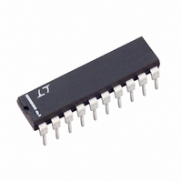
LT1161CN Linear Technology, LT1161CN Datasheet - Page 4

LT1161CN
Manufacturer Part Number
LT1161CN
Description
IC MOSFET DRIVER N-CH QUAD 20DIP
Manufacturer
Linear Technology
Datasheet
1.LT1161CSWPBF.pdf
(12 pages)
Specifications of LT1161CN
Configuration
High-Side
Input Type
Non-Inverting
Delay Time
220µs
Number Of Configurations
4
Number Of Outputs
4
Voltage - Supply
8 V ~ 48 V
Operating Temperature
0°C ~ 70°C
Mounting Type
Through Hole
Package / Case
20-DIP (0.300", 7.62mm)
Lead Free Status / RoHS Status
Contains lead / RoHS non-compliant
Current - Peak
-
High Side Voltage - Max (bootstrap)
-
Available stocks
Company
Part Number
Manufacturer
Quantity
Price
Part Number:
LT1161CN
Manufacturer:
LT/凌特
Quantity:
20 000
Part Number:
LT1161CN#PBF
Manufacturer:
LINEAR/凌特
Quantity:
20 000
PIN
FUNCTIONAL DIAGRA
LT1161
Supply Pins: The two supply pins are internally connected
and must also be externally connected. In addition to
providing the operating current for the LT1161, the supply
pins also serve as the Kelvin connection for the current
sense comparators. The supply pins must be connected to
the positive side of the drain sense resistors for proper
operation of the current sense.
Input Pins: The input pins are active high and each pin
activates a separate internal charge pump when switched
ON. The input threshold is TTL/CMOS compatible but may
be taken as high as 15V with or without the supply
powered. Each input has approximately 200mV of hyster-
esis and an internal 75k pull-down resistor.
Gate Pins: The gate pins drive the power MOSFET gates.
When an input is ON, the corresponding gate pin is
pumped approximately 12V above the supply. These pins
have a relatively high impedance when above the rail (the
equivalent of a few hundred kilohms). Care should be
taken to minimize any loading by parasitic resistance to
ground or supply.
Sense Pins: Each sense pin connects to the input of a
supply-referenced comparator with a 65mV nominal off-
set. When a sense pin is taken more than 65mV below
4
U
U
FUNCTIONS
U
U
TIMER
INPUT
14µA
U
75k
1.4V
3V
75k
W
+
–
+
–
(Each Channel)
–
+
1.4V
supply, the MOSFET gate for that channel is driven low and
the corresponding timing capacitor discharged. Each cur-
rent-sense comparator operates completely independently.
The 65mV typical threshold has a +0.33%/°C temperature
coefficient, which closely matches the TC of drain sense
resistors formed from copper PC traces.
Some loads require high in-rush currents. An RC time
delay can be added between the drain sense resistor and
the sense pin to ensure that the current-sense comparator
does not false trigger during start-up (see Applications
Information). However, a maximum of 10kΩ can be in-
serted between a drain sense resistor and the sense pin. If
current sense is not required in any channel, the sense pin
for that channel is tied to supply.
Timer Pins: A timing capacitor C
ground sets the restart time following overcurrent detec-
tion. C
recharged by a 14µA nominal current source back to the
timer threshold, whereupon restart is attempted. If current
sense is not required in any channel, the timer pin for that
channel is left open.
Ground Pins: The two ground pins are internally con-
nected and must also be externally connected.
T
is rapidly discharged to less than 1V and then
CHARGE PUMP
OSCILLATOR
AND
–
+
T
V
+
from each timer pin to
65mV
1161 FD
GATE
SENSE
1161fa


