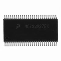
MCZ33927EK Freescale Semiconductor, MCZ33927EK Datasheet - Page 34

MCZ33927EK
Manufacturer Part Number
MCZ33927EK
Description
IC FET PRE-DRIVER 3PH 54-SOIC
Manufacturer
Freescale Semiconductor
Specifications of MCZ33927EK
Configuration
3 Phase Bridge
Input Type
Inverting and Non-Inverting
Delay Time
265ns
Current - Peak
600mA
Number Of Configurations
1
Number Of Outputs
3
High Side Voltage - Max (bootstrap)
75V
Voltage - Supply
8 V ~ 40 V
Operating Temperature
-40°C ~ 125°C
Mounting Type
Surface Mount
Package / Case
54-SOIC (7.5mm Width) Exposed Pad, 54-eSOIC, 54-HSOIC
Lead Free Status / RoHS Status
Lead free / RoHS Compliant
Available stocks
Company
Part Number
Manufacturer
Quantity
Price
Status Register 1 (MODE Bits)
the following data:
Status Register 2 (MASK bits)
the following data:
Status Register 3 (Deadtime)
the following data:
34
Table 15. Status Register 1
Table 16. Status Register 2
Table 17. Status Register 3
33927
FUNCTIONAL DEVICE OPERATION
LOGIC COMMANDS AND REGISTERS
yet performed, all these bits return 0 even though the actual dead time is the maximum.
SPI Data Bits
Results
Register 1
Read
Reset
SPI Data Bits
Results
Register 2
Read
Reset
SPI Data Bits
Results
Register 3
Read
Reset
This register is read by sending the NULL1 command (000x xx01). This is guaranteed to not affect IC operation and returns
This register is read by sending the NULL2 command (000x xx10). This is guaranteed to not affect IC operation and returns
This register is read by sending the NULL3 command (000x xx11). This is guaranteed to not affect IC operation and returns
• Bit 0 – Lock Bit indicates the IC registers (Deadtime, MASKn, CLINTn, and Mode) are locked. Any subsequent write to
• Bit 1 – is the present status of FULLON Mode . If this bit is set to “0”, the FULLON mode is not allowed. A “1” indicates the
• Bit 3 –indicates Deadtime Calibration occurred. It will be “0” until a successful Deadtime command is executed. This
• Bit 4 –is a flag for a Deadtime Calibration Overflow .
• Bit 5 –is set if Zero Deadtime is commanded.
• Bit 6 –reflects the current state of the Desaturation/Phase Error turn-off mode.
These bits represent the calibration applied to the internal oscillator to generate the requested deadtime. If calibration is not
these registers is ignored and will set the Write Error flag.
IC can operate in FULLON Mode (both High-Side and Low-Side FETs of one phase can be simultaneously turned on).
includes the Zero Deadtime setting, as well as a Calibration Overflow.
Mask1:3
Dead7
7
0
0
7
1
7
0
Desaturation
Mask1:2
Dead6
Mode
6
0
6
1
6
0
Deadtime
Mask1:1
Dead5
Zero
Set
5
0
5
1
5
0
Calibration
Overflow
Mask1:0
Dead4
4
0
4
1
4
0
Calibration
Deadtime
Mask0:3
Dead3
3
0
3
1
3
0
Mask0:2
Analog Integrated Circuit Device Data
Dead2
2
0
0
2
1
2
0
Freescale Semiconductor
FULLON
Mask0:1
Dead1
Mode
1
0
1
1
1
0
Mask0:0
Dead0
Lock
Bit
0
0
0
1
0
0


