L295 STMicroelectronics, L295 Datasheet

IC DRVR SWITCH DUAL MULTIWATT15

L295

Manufacturer Part Number
L295
Description
IC DRVR SWITCH DUAL MULTIWATT15
Manufacturer
STMicroelectronics
Datasheet

Specifications of L295

Applications
DC Motor Driver
Number Of Outputs
2
Current - Output
2A
Voltage - Supply
12 V ~ 46 V
Operating Temperature
-40°C ~ 150°C
Mounting Type
Through Hole
Package / Case
Multiwatt-15 (Vertical, Bent and Staggered Leads)
Maximum Operating Temperature
+ 150 C
Minimum Operating Temperature
- 40 C
Maximum Power Dissipation
25000 mW
Mounting Style
Through Hole
Supply Voltage Min
12V
Supply Voltage Max
46V
No. Of Outputs
4
Output Voltage
2.8V
Output Current
2A
Driver Case Style
Multiwatt
Device Type
Motor
Filter Terminals
Through Hole
Rohs Compliant
Yes
Lead Free Status / RoHS Status
Lead free / RoHS Compliant
Voltage - Load
-
Lead Free Status / Rohs Status
Lead free / RoHS Compliant
Other names
497-1391-5

Available stocks

Company
Part Number
Manufacturer
Quantity
Price
Part Number:
L295
Manufacturer:
HYNIX
Quantity:
101
Part Number:
L295
Manufacturer:
ST
Quantity:
5 510
Part Number:
L295
Manufacturer:
ST
0
Part Number:
L295
Quantity:
400
Part Number:
L295H
Quantity:
800
Part Number:
L295N-
Manufacturer:
ST
0
Part Number:
L295V
Manufacturer:
ST
Quantity:
20 000
DESCRIPTION
The L295 is a monolithic integrated circuit in a 15
-lead Multiwatt® package; it incorporates all the
functions for direct interfacing between digital cir-
cuitry and inductive loads.
The L295 is designed to accept standard micro-
processor logic levels at the inputs and can drive
2 solenoids. The output current is completely con-
BLOCK DIAGRAM
October 2003
HIGH CURRENT CAPABILITY (up to 2.5A per
channel)
HIGH VOLTAGE OPERATION (up to 46V for
power stage)
HIGH EFFICIENCY SWITCHMODE
OPERATION
REGULATED OUTPUT CURRENT
(adjustable)
FEW EXTERNAL COMPONENTS
SEPARATE LOGIC SUPPLY
THERMAL PROTECTION
V
+V
REF2
+V
SS
S
D3
D4
R
S2
R2
L2
10
1
15
14
13
12
REGULATOR
VOLTAGE
DRIVER
DRIVER
H2
L2
DUAL SWITCH-MODE SOLENOID DRIVER
CIRCUITS
LOGIC
SHUTDOWN
THERMAL
Q
S
FF2
R
11
V
in2
7
EN
6
V
trolled by means of a switch-ing technique allow-
ing very efficient operation.
Furthermore, it includes an enable input and dual
supplies (for interfacing with peripherals running at
a higher voltage than the logic).
The L295 is particularly suitable for applications
such as hammer driving in matrix printers, step
motor driving and electromagnet controllers.
in1
OSCILLATOR
C
9
FF2
R
S
Q
R
CIRCUITS
ORDERING NUMBER: L295
LOGIC
MULTIWATT15
DRIVER
DRIVER
D03IN1503
H1
L1
1
2
3
4
5
8
R1
L1
D1
D2
L295
+V
V
REF1
S
1/7

Related parts for L295

L295 Summary of contents

Page 1

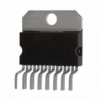
... FEW EXTERNAL COMPONENTS SEPARATE LOGIC SUPPLY THERMAL PROTECTION DESCRIPTION The L295 is a monolithic integrated circuit -lead Multiwatt® package; it incorporates all the functions for direct interfacing between digital cir- cuitry and inductive loads. The L295 is designed to accept standard micro- processor logic levels at the inputs and can drive 2 solenoids ...

Page 2

... L295 ABSOLUTE MAXIMUM RATINGS Symbol V Supply voltage S V Logic supply voltage SS , Enable and input voltage Reference voltage ref I Peak output current (each channel non repetitive (t = 100 sec) - repetitive (80 20% off operation P Total power dissipation (at T tot Storage and junction temperature stg ...

Page 3

... D1 High speed diodes trr 200 FUNCTIONAL DESCRIPTION The L295 incorporates two indipendent driver channals with separate inputs and outputs, each capable of driving an inductive load (see block diagram). The device is controlled by three micriprocessor compatible digital inputs and two analog inputs. Test Condition Low ...

Page 4

... I and a lower holding current I p The L295 is provided with a thermal protection that switches off all the output transistors when the junction temperature exceeds 150°C. The presence of a hysteresis circuit makes the IC work again aftera fall of 4/7 for V etc ...

Page 5

... ON Q2 OFF ) can be left open or connected to V ref2 2 ------- - Figure 3. With D03IN1504 Figure 4. Switching frequency vs. values of R and C. f (KHz D03IN1505 ; in this case the circuit works with ss changed by hardware. ref REF ON Q1 OFF ON Q2 OFF D03IN1506 Rmin 100 L295 : D03IN1507 R(K ) 5/7 ...

Page 6

... L295 mm DIM. MIN. TYP. MAX 2. 0.49 0.55 0.019 F 0.66 0.75 0.026 G 1.02 1.27 1.52 0.040 G1 17.53 17.78 18.03 0.690 H1 19.6 0.772 H2 20.2 L 21.9 22.2 22.5 0.862 L1 21.7 22.1 22.5 0.854 L2 17.65 18.1 0.695 L3 17.25 17.5 17.75 0.679 L4 10.3 10.7 10 ...

Page 7

... L295 Information furnished is believed to be accurate and reliable. However, STMicroelectronics assumes no responsibility for the consequences of use of such information nor for any infringement of patents or other rights of third parties which may result from its use. No license is granted by implication or otherwise under any patent or patent rights of STMicroelectronics. Specifications mentioned in this publication are subject to change without notice ...

Related keywords