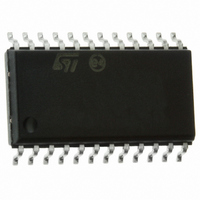
L6219DSA STMicroelectronics, L6219DSA Datasheet - Page 9

L6219DSA
Manufacturer Part Number
L6219DSA
Description
IC STEPPER MOTOR DRIVER SO-24
Manufacturer
STMicroelectronics
Type
Driverr
Datasheet
1.L6219DSA13TR.pdf
(15 pages)
Specifications of L6219DSA
Applications
DC Motor Driver, Stepper Motor Driver
Number Of Outputs
2/1
Current - Output
±750mA
Voltage - Load
10 V ~ 46 V
Voltage - Supply
4.75 V ~ 5.25 V
Operating Temperature
-40°C ~ 125°C
Mounting Type
Surface Mount
Package / Case
24-SOIC (7.5mm Width)
Product
Stepper Motor Controllers / Drivers
Operating Supply Voltage
10 V to 46 V
Supply Current
0.01 A
Mounting Style
SMD/SMT
Lead Free Status / RoHS Status
Lead free / RoHS Compliant
Available stocks
Company
Part Number
Manufacturer
Quantity
Price
Company:
Part Number:
L6219DSA
Manufacturer:
ST
Quantity:
5 510
Company:
Part Number:
L6219DSA
Manufacturer:
SIEMENS
Quantity:
5 510
L6219DSA
2
2.1
2.2
2.3
Functional description
The circuit is intended to drive both windings of a bipolar stepper motor.
The peak current control is generated through switch mode regulation.There is a choice of
three different current levels with the two logic inputs I
winding 2.
The current can also be switched off completely.
Input logic (I
The current level in the motor winding is selected with these inputs. (See
the logic inputs is left open, the circuit will treat it has a high level input.
Table 6.
Phase
This input determines the direction of current flow in the windings, depending on the motor
connections. The signal is fed through a schmidt-trigger for noise immunity, and through a
time delay in order to guarantee that no short-circuit occurs in the output stage during
phase-shift.High level on the phase input causes the motor current flow from out A through
the winding to out B.
Current sensor
This part contains a current sensing resistor (R
comparators. Only one comparator is active at a time. It is activated by the input logic
according to the current level chosen with signals I
the sensing resistor R
becomes higher than the reference voltage on the other comparator input, the comparator
goes high, which triggers the pulse generator.
The max peak current I
I
H
H
L
L
0
Current levels
0
and I
S
. When the current has increased so that the voltage across R
max
I
H
H
L
L
1
can be defined by:
1
)
No current
Low current 1/3 I
Medium current 2/3 I
Maximum current I
I
max
=
-------------
10R
V
S
ref
), a low pass filter (R
o
s
O
and I
O
max
01
O
max
max
- I
1
Current level
. The motor current flows through
11
for winding 1 and I
Functional description
C
, C
Figure
C
) and three
02
4). If any of
- I
12
S
for
9/15


