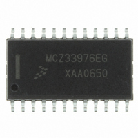
MCZ33976EG Freescale Semiconductor, MCZ33976EG Datasheet - Page 27

MCZ33976EG
Manufacturer Part Number
MCZ33976EG
Description
IC DRIVER DUAL GAUGE SPI 24-SOIC
Manufacturer
Freescale Semiconductor
Type
Serial Peripheral Interface (SPI) Dual Step Motor Gauge Driverr
Datasheet
1.MCZ33976EG.pdf
(41 pages)
Specifications of MCZ33976EG
Applications
Stepper Motor Driver, 2 Phase
Number Of Outputs
2
Current - Output
100mA
Voltage - Supply
6.5 V ~ 26 V
Operating Temperature
-40°C ~ 125°C
Mounting Type
Surface Mount
Package / Case
24-SOIC (7.5mm Width)
Supply Current
4 mA
Maximum Operating Temperature
+ 125 C
Mounting Style
SMD/SMT
Minimum Operating Temperature
- 40 C
Lead Free Status / RoHS Status
Lead free / RoHS Compliant
Voltage - Load
-
Lead Free Status / Rohs Status
Lead free / RoHS Compliant
Available stocks
Company
Part Number
Manufacturer
Quantity
Price
Part Number:
MCZ33976EG
Manufacturer:
FREESCALE
Quantity:
20 000
Table 29. Coil Step Value
intervals. The time between steps defines the motor velocity,
and the changing time defines the motor acceleration.
and also the maximum velocity. A useful side effect of the
table is that it also allows the direct determination of the
position at which the velocity should reduce to stop the motor
at the desired position.
(The units of position are steps, and velocity and acceleration
are in steps/second and steps/second².)
motor position (s) at a time (t) is:
motor is initially travelling at a velocity u. In the ROM, this time
is quantized to multiples of the system clock by rounding
upwards, ensuring acceleration never exceeds the allowed
value. The actual velocity and acceleration is calculated from
the time step actually used.
Analog Integrated Circuit Device Data
Freescale Semiconductor
* Denotes normalized values.
The motor is stepped by providing index commands at
The state machine uses a table to define the allowed time
The motor equations of motion are generated as follows.
From an initial position of 0 with an initial velocity (u), the
For unit steps, the time between steps is:
This defines the time increment between steps when the
Using|
14
15
16
17
18
19
20
21
22
23
210
225
240
255
270
285
300
315
330
345
⇒
-0.707
-0.866
-0.966
-0.966
-0.866
-0.707
-0.259
t
s
-0.5
-0.5
-1
=
v
=
2
v = u + at
−
= u
ut
u
and
+
2
+
+ 2as
a
u
1
-0.867
-0.707
-0.259
2
0.259
0.707
0.866
0.966
2
-0.5
0.5
at
0
+
2
2
a
-0.966
-0.866
-0.707
-0.500
-0.259
0.259
0.500
0.707
-1
0
quantized value obtained above.
generated to give the allowed time step between motor
indexes when the motor is accelerating from a stop to its
maximum velocity.
equations define the time interval between steps at each
position. To drive the motor at maximum performance, index
commands are given to the motor at these intervals. A table
is generated giving the time step
indexed by n positions and has been accelerating steadily at
the maximum allowed rate. This is critical because it also
indicates the minimum distance the motor must travel while
decelerating to a stop. For example, the stopping distance is
also equal to the current value of n.
provided in
4800 microsteps/s (at 12 microsteps/degrees), and its
maximum acceleration is 54000 microsteps/s
quantized to a 1.0 MHz clock.
1. While the motor is stopped, wait until a command is
2. Send index pulses to the motor at an ever-increasing
and solving for v in terms of u, s, and t gives:
The correct value of t to use in this equation is the
From these equations a set of recursive equations can be
Starting from a position p of 0 and a velocity v of 0, these
where
Note P
The algorithm to drive the motor is similar to:
An example of the velocity table for a particular motor is
received.
rate, according to the time steps in
a. The maximum velocity is reached, at which point
b. The distance remaining to travel is less than the
the time intervals stop decreasing, or
current index in the table. At this point, the stopping
distance is equal to the remaining distance, and to
ensure it will stop at the required position, the motor
must begin decelerating.
⎡ ⎤
n
Table
= n
indicates rounding up.
.
This means on the n th step the motor has
30. This motor’s maximum speed is
v
n
LOGIC COMMANDS AND REGISTERS
=
v =
FUNCTIONAL DEVICE OPERATION
v
p
2
P
0
0
n
2
∆
/
=
=
= n
t
t
n
0
0
- u
∆
−
t at an index position n.
v
n
−
1
Table 30
2
. The table is
until:
33976
27


