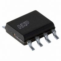
TEA1791T/N1,118 NXP Semiconductors, TEA1791T/N1,118 Datasheet

TEA1791T/N1,118
Specifications of TEA1791T/N1,118
Related parts for TEA1791T/N1,118
TEA1791T/N1,118 Summary of contents
Page 1
TEA1791T GreenChip synchronous rectifier controller Rev. 02 — 7 June 2010 1. General description The TEA1791T is a member of the new generation of Synchronous Rectifier (SR) controller ICs for switched mode power supplies. Its high level of integration allows ...
Page 2
... NXP Semiconductors 5. Block diagram SRSENSE Fig 1. 6. Pinning information 6.1 Pinning Fig 2. 6.2 Pin description Table 2. Symbol SRSENSE GND n.c. DRIVER n.c n.c. n. TEA1791T Product data sheet 1 control Q TIMER 2 μs 4 DRIVER Q 2.2 μ n.c. Block diagram SRSENSE GND n.c. DRIVER Pin configuration ...
Page 3
... NXP Semiconductors 7. Functional description 7.1 Introduction The TEA1791T is the controller for synchronous rectification to be used in discontinuous conduction mode and quasi-resonant flyback converters. 7.2 Start-up and UnderVoltage LockOut (UVLO) The IC leaves the undervoltage lockout state and activates the synchronous rectifier circuitry as soon as the voltage on the V drops below 8 ...
Page 4
... NXP Semiconductors V SRSENSE Secondary V Fig 3. If the secondary stroke of the flyback converter is shorter than 2 μs (typical), the driver output is disabled. This will guarantee stable operation for very low duty cycles. When the secondary stroke increases above 2.2 μs (typical), the driver output is again enabled. ...
Page 5
... NXP Semiconductors 8. Limiting values Table 3. In accordance with the Absolute Maximum Rating System (IEC 60134). All voltages are measured with respect to ground (pin 2); positive currents flow into the chip. The voltage ratings and current ratings are valid provided the other ratings are not violated. ...
Page 6
... NXP Semiconductors 10. Characteristics Table 5. Characteristics ° all voltages are measured with respect to ground (pin 2); currents are positive when flowing into amb CC the IC; unless otherwise specified. Symbol Parameter Supply voltage management (pin V V start-up voltage startup V hysteresis voltage hys I operating supply current V ...
Page 7
... NXP Semiconductors 11. Application information A switched mode power supply with the TEA1791T consists of a primary side discontinuous conduction mode flyback controller, a transformer, and an output stage with a feedback circuit. A MOSFET (Q This MOSFET is controlled by the TEA1791T. The timing for the synchronous rectifier switch is derived from the voltage sensed on the SRSENSE pin ...
Page 8
... NXP Semiconductors 12. Package outline SO8: plastic small outline package; 8 leads; body width 3 pin 1 index 1 DIMENSIONS (inch dimensions are derived from the original mm dimensions) A UNIT max. 0.25 1.45 mm 1.75 0.25 0.10 1.25 0.010 0.057 inches 0.069 0.01 0.004 0.049 Notes 1. Plastic or metal protrusions of 0.15 mm (0.006 inch) maximum per side are not included. ...
Page 9
... NXP Semiconductors 13. Revision history Table 6. Revision history Document ID Release date TEA1791T v.2 20100607 • Modifications: R • Figure 5 “Application diagram low side • Minimum value junction temperature changed in TEA1791T_1 20090203 TEA1791T Product data sheet Data sheet status Product data sheet added to Table 4 ...
Page 10
... In no event shall NXP Semiconductors be liable for any indirect, incidental, punitive, special or consequential damages (including - without limitation - lost profits, lost savings, business interruption, costs related to the removal or ...
Page 11
... For sales office addresses, please send an email to: TEA1791T Product data sheet own risk, and (c) customer fully indemnifies NXP Semiconductors for any liability, damages or failed product claims resulting from customer design and use of the product for automotive applications beyond NXP Semiconductors’ ...
Page 12
... NXP Semiconductors 16. Contents 1 General description . . . . . . . . . . . . . . . . . . . . . . 1 2 Features and benefits . . . . . . . . . . . . . . . . . . . . 1 2.1 Distinctive features . . . . . . . . . . . . . . . . . . . . . . 1 2.2 Green features . . . . . . . . . . . . . . . . . . . . . . . . . 1 2.3 Protection features . . . . . . . . . . . . . . . . . . . . . . 1 3 Applications . . . . . . . . . . . . . . . . . . . . . . . . . . . . 1 4 Ordering information . . . . . . . . . . . . . . . . . . . . . 1 5 Block diagram . . . . . . . . . . . . . . . . . . . . . . . . . . 2 6 Pinning information . . . . . . . . . . . . . . . . . . . . . . 2 6.1 Pinning . . . . . . . . . . . . . . . . . . . . . . . . . . . . . . . 2 6.2 Pin description . . . . . . . . . . . . . . . . . . . . . . . . . 2 7 Functional description . . . . . . . . . . . . . . . . . . . 3 7.1 Introduction 7.2 Start-up and UnderVoltage LockOut (UVLO ...


