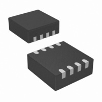
STM6505RCABDG6F STMicroelectronics, STM6505RCABDG6F Datasheet - Page 7

STM6505RCABDG6F
Manufacturer Part Number
STM6505RCABDG6F
Description
IC SMART RESET DUAL PB 8TDFN
Manufacturer
STMicroelectronics
Series
Smart Reset™r
Type
Smart Resetr
Specifications of STM6505RCABDG6F
Number Of Voltages Monitored
1
Output
Open Drain or Open Collector
Reset
Active Low
Reset Timeout
240 ms Minimum
Voltage - Threshold
2.625V
Operating Temperature
-40°C ~ 85°C
Mounting Type
Surface Mount
Package / Case
8-TDFN
Current - Supply
2.3µA
Voltage - Supply
1 V ~ 5.5 V
Applications
General Purpose
Supply Voltage (max)
7 V
Supply Voltage (min)
- 0.3 V
Maximum Operating Temperature
+ 85 C
Minimum Operating Temperature
- 40 C
Mounting Style
SMD/SMT
Number Of Switches
Dual
Supply Current
2.2 uA
Lead Free Status / RoHS Status
Lead free / RoHS Compliant
Other names
497-10531-2
STM6502, STM6503, STM6504, STM6505
Table 2.
Symbol
SRC
V
RST
SRE
TSR
BLD
SR0
SR1
V
V
NC
BAT
CC
SS
output
Output
Output
Supply
Supply
Input/
Input
Input
Input
Input
Input
Input
Signal names
Open-drain reset output, active-low.
Battery low detect output, active-low, open-drain. STM6505 only.
Primary push-button Smart Reset input. Active-low, with or without internal
65 kΩ pull-up to V
Secondary push-button Smart Reset input - combines with the primary push-
button reset to provide setup delay time before reset. Active-low, with or without
internal 65 kΩ pull-up to V
Secondary push-button Smart Reset input - provides instant Smart Reset. SRE
is edge-triggered with a special debounce time (t
the falling edge after a valid reset period. Active-high, no internal pull-up to V
STM6504 only.
Smart Reset input delay setup control: connect to an external capacitor to adjust
the delay setup time (t
A three-state Smart Reset input delay setup control. When connected to
ground, t
t
either permanently grounded, permanently connected to V
left open. If left open, for improved system glitch immunity it is strongly
recommended to connect a 0.1 µF decoupling ceramic capacitor between the
TSR and V
Supply voltage input. Power supply for the device and an input for the monitored
supply voltage. A 0.1 µF decoupling ceramic capacitor is recommended to be
connected between the V
Battery voltage monitoring input. STM6505 only.
Ground
No connect (not bonded); should be connected to V
SRC
= 10 s (all times are minimum). TSR is a DC-type input, intended to be
SRC
SS
Doc ID 16101 Rev 6
= 2 s; when left open, t
pins. STM6503 and STM6504 only.
CC
(product options).
SRC
CC
CC
). STM6502 and STM6505 only.
and V
(product options).
Description
SS
SRC
pins.
= 6 s; when connected to V
DEBOUNCE
SS
.
CC
= 240 ms min.) at
or permanently
Description
CC
,
CC
7/29
.


