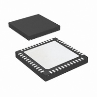
LP3913SQ-ADJ/NOPB National Semiconductor, LP3913SQ-ADJ/NOPB Datasheet - Page 29

LP3913SQ-ADJ/NOPB
Manufacturer Part Number
LP3913SQ-ADJ/NOPB
Description
IC POWER MANAGEMENT 48-LLP
Manufacturer
National Semiconductor
Series
PowerWise®r
Datasheet
1.LP3913SQ-ACNOPB.pdf
(58 pages)
Specifications of LP3913SQ-ADJ/NOPB
Applications
Handheld/Mobile Devices
Voltage - Supply
2.5 V ~ 6 V
Operating Temperature
-40°C ~ 85°C
Mounting Type
Surface Mount
Package / Case
48-LLP
Lead Free Status / RoHS Status
Lead free / RoHS Compliant
Current - Supply
-
Other names
LP3913SQ-ADJ
LP3913SQ-ADJ
LP3913SQ-ADJTR
LP3913SQ-ADJ
LP3913SQ-ADJTR
Transitioning From Active Mode To Standby Mode
External Event Triggers the Transition from Active to
Standby Mode
When the device is active, a subsequent re-assertion of the
push button will turn off the LP3913 indirectly by first flagging
the system processor though the ONSTAT pin. Upon detect-
ing the ONSTAT transition, the system processor must clear
bit D4 (PACK) in the Power On Event Register and apply a
logic low to the POWERACK pin to power down the LP3913,
which then transitions to Standby Mode. Clearing the PACK
Power Up Sequence
29
register bit and POWERACK pin while external supply
sources are present (either USB or CHG_IN) will not power
down the LP3913, to keep the charger active. The system can
as always disable all necessary DC/DC converters, except
BUCK1, through the register control.
When external power is disconnected, LP3913 will remain in
its Active state unless the battery voltage is below V
tery Low Alarm) or unless the PACK (either bit D4 in the PON
register and the POWERACK pin) is cleared by the system
processor.
www.national.com
BLA
30000106
(Bat-


