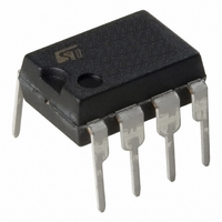
L9686 STMicroelectronics, L9686 Datasheet - Page 3

L9686
Manufacturer Part Number
L9686
Description
IC DIRECTION INDICATOR 8-MINIDIP
Manufacturer
STMicroelectronics
Datasheet
1.L9686MD.pdf
(7 pages)
Specifications of L9686
Applications
Automotive
Voltage - Supply
8 V ~ 18 V
Operating Temperature
-20°C ~ 100°C
Mounting Type
Through Hole
Package / Case
8-DIP (0.300", 7.62mm)
Operating Supply Voltage
80 V
Maximum Operating Temperature
+ 150 C
Mounting Style
Through Hole
Minimum Operating Temperature
- 55 C
Lead Free Status / RoHS Status
Lead free / RoHS Compliant
Current - Supply
-
Lead Free Status / Rohs Status
No
Available stocks
Company
Part Number
Manufacturer
Quantity
Price
Company:
Part Number:
L9686
Manufacturer:
TOSHIBA
Quantity:
3 334
Part Number:
L9686
Manufacturer:
ST
Quantity:
20 000
Part Number:
L9686D
Manufacturer:
HUAAO
Quantity:
20 000
Part Number:
L9686MD
Manufacturer:
ST
Quantity:
20 000
Part Number:
L9686MD013TR
Manufacturer:
ST
Quantity:
20 000
ELECTRICAL CHARACTERISTICS (– 20 C < T
fied.)
Notes : 1.
FUNCTIONAL DESCRIPTION
The circuit is designed to drive the direction indi-
cator flasher relay. The application circuit shows
the typical system configuration with the external
components. Its consists of a network (R
determine the oscillator frequency, shunt resistor
(R
iting resistors (R
load dump transients.
The lightbulbs L
dicators with the dashboard-light L
switch position is sensed across resistor R
and R
S
Symbol
V2 – V1
V2 – V3
) to detect defective bulbs and two current lim-
DC
D.C.
R2
V
V
K
C
K
I
Q
2.
3.
4.
5.
lamp
th
S
N
C
T
LF
This voltage is the threshold used to protect the circuit against overvoltage : if V
and the voltage across the circuit will maintain constant increasing the current in the protective resistor R
This is the maximum value for operation. This value must be higher than 1 K Ohms in order to limit the current in pin 8 during
dumps. A recommended value for application should be 1,5 K Ohms.
The external leakage from the blinker unit to ground must be with an equivalent resistor higher than 5,6 K Ohms to avoid para-
sitic operation when the switch S
This temperature coefficient is usefull to compensate the drift of the external timing network (R
This threshold is calculated for a 20 m Ohm shunt. The threshold is dependant of V
by input 8. The flashing cycle is started
Operating Voltage
Clamping Voltage
Output Saturation Voltage
Starter Resistance
Oscillator Constant K
Operation)
Temperature Coefficient of Kn
Duty Cycle (normal operation)
Oscillator Constant K
(lamp failure detection)
Duty Cicle (lamp failure
detection)
Current Consumption Relay off
I
Lamp Failure Threshold
(see note 4)
pin 1
2
, L
2
/R
3
, L
3
) to protect the IC against
Parameter
4
, L
5
, are the turn signal in-
N
C
(normal
1
is off.
6
. The S
1
See Note 3
see note 1
I
see note 2
Fn = 1/KnRoCo
Osc. Frequency
F
Osc. Frequency
V
V
V
R
V
–20 < T
C
RL
C
S
S
S
S
3
1
= 1KcRoCo
= 8V
= 13.5V
= 18V
= 220
= 13.5V
) to
= 250mA
1
2
amb
amb
Test Condition
< 100 C
<, 100 C, 8V < V
by closing S
equal to 1.5 ms, the relay is actuated and the pin
3 goes high switching on the corresponding
lamps L
the oscillator frequency not depending on the bat-
tery voltage value (8 - 18 V). The flashing cycle
stops and the circuit is reset to the initial position
when the switch S
The lamp failure detection function senses the
current through the shunt resistor R
of the lightbulbs is defective the voltage drop
across R
indicated by doubling the flashing frequency.
2
, L
S
is reduced to a half and the failure is
3
1
, (or L
: then, after a delay time t
bat
bat
S
is > than this threshold, the relay will be on
1
4
as the bulb current.
< 18V unless otherwise speci-
, L
is open.
Min.
1.27
0.53
27
45
35
65
8
5
). These lamps will flash at
1
, C
–1.5
Typ.
10-3
1
2.2
2.7
3.3
).
50
40
85
3
.
Max.
1.74
0.74
1.7
3.6
3.9
4.3
4.7
18
34
55
45
95
S
. When one
d
typically
L9686
Unit
1/ C
mA
mA
mA
mV
K
%
%
V
V
V
3/7


