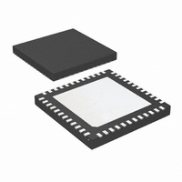
LM96194CISQ/NOPB National Semiconductor, LM96194CISQ/NOPB Datasheet - Page 22

LM96194CISQ/NOPB
Manufacturer Part Number
LM96194CISQ/NOPB
Description
IC TRUTHERM HDWR MONITOR 48-LLP
Manufacturer
National Semiconductor
Series
PowerWise®, TruTherm®r
Datasheet
1.LM96194CISQNOPB.pdf
(106 pages)
Specifications of LM96194CISQ/NOPB
Function
Fan Control, Temp Monitor
Topology
ADC (Sigma Delta), Comparator, Fan Control, Multiplexer, Register Bank
Sensor Type
External & Internal
Sensing Temperature
-40°C ~ 85°C, External Sensor
Output Type
SMBus™
Output Alarm
No
Output Fan
Yes
Voltage - Supply
3 V ~ 3.6 V
Operating Temperature
-40°C ~ 85°C
Mounting Type
Surface Mount
Package / Case
48-LLP
Lead Free Status / RoHS Status
Lead free / RoHS Compliant
Other names
LM96194CISQTR
www.national.com
14.5.4 Read Operations
The LM96194 uses the following SMBus read protocols.
14.5.4.1 Read Byte
In the LM96194, the read byte protocol is used to read a single byte of data from a register. In this operation the master device
receives a single byte from a slave device, as follows:
1.
2.
3.
4.
5.
6.
7.
8.
9.
10. The master asserts a STOP condition and the transaction ends.
14.5.4.2 Read Word
In the LM96194, the read word protocol is used to read two bytes of data from a register or two consecutive registers. In this
operation the master device reads two bytes from a slave device, as follows:
1.
2.
3.
4.
5.
6.
7.
8.
9.
10. The master receives the High data byte and asserts a NACK.
11. The master asserts a STOP condition and the transaction ends.
14.5.4.3 SMBus Block-Write Block-Read Process Call
This transaction is used to read a block of data from the LM96194. Below is the sequence of events that occur in this transaction:
1.
2.
3.
4.
5.
6.
7.
8.
9.
10. The slave asserts ACK.
11. The master receives a byte count data byte that tells it how many data bytes will received. This field reflects the number of
The master device asserts a START condition.
The master sends the 7-bit slave address followed by the write bit (low).
The addressed slave device asserts ACK.
The master sends a register address.
The slave asserts an ACK.
The master sends a Repeated START.
The master sends the slave address followed by the read bit (high).
The slave asserts an ACK.
The master receives a data byte and asserts a NACK.
The master device asserts a START condition.
The master sends the 7-bit slave address followed by the write bit (low).
The addressed slave device asserts ACK.
The master sends a register address.
The slave asserts an ACK.
The master sends a Repeated START.
The master sends the slave address followed by the read bit (high).
The slave asserts an ACK.
The master receives the Low data byte and asserts an ACK.
The master device asserts a START condition.
The master sends the 7-bit slave address followed by the write bit (low).
The addressed slave device asserts ACK.
The master sends a command code that tells the slave device to expect a block read (F1h) and the slave asserts ACK.
The master sends the Byte Count for this write which is 2 and the slave asserts ACK.
The master sends the Start Register Address for the block read and the slave asserts the ACK.
The master sends the Byte Count (1-32) for the block read processes call and the slave asserts ACK.
The master asserts a repeat START condition.
The master sends the 7-bit slave address followed by the read bit (high).
bytes requested by the Byte Count transmitted to the LM96194. The SMBus specification allows a maximum of 32 data bytes
to be received in a block read. Then master asserts ACK.
1
S
2
Slave
Address
1
S
2
Slave
Address
W
3
A
W
4
Register
Address
3
A
4
Register
Address
5
A
6
S
5
A
7
Slave
Address
6
S
22
7
Slave
Address
R
8
A
R
9
Data
Byte Low
8
A
9
Data
Byte
A
10
Data
Byte High
/A
10
P
/A
11
P


