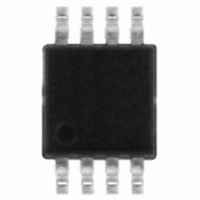
STTS75DS2F STMicroelectronics, STTS75DS2F Datasheet - Page 22

STTS75DS2F
Manufacturer Part Number
STTS75DS2F
Description
IC TEMP SENSOR DGTL WCHDG 8MSOP
Manufacturer
STMicroelectronics
Datasheet
1.STTS75M2F.pdf
(41 pages)
Specifications of STTS75DS2F
Function
Temp Sensor, Watchdog
Topology
ADC (Sigma Delta), Comparator, Register Bank
Sensor Type
Internal
Sensing Temperature
-55°C ~ 125°C
Output Type
I²C™/SMBus™
Output Alarm
Yes
Output Fan
No
Voltage - Supply
2.7 V ~ 5.5 V
Operating Temperature
-55°C ~ 125°C
Mounting Type
Surface Mount
Package / Case
8-MSOP, Micro8™, 8-uMAX, 8-uSOP,
Full Temp Accuracy
+/- 3 C
Digital Output - Bus Interface
Serial (2-Wire, I2C)
Digital Output - Number Of Bits
12 bit
Maximum Operating Temperature
+ 125 C
Minimum Operating Temperature
- 55 C
For Use With
497-8844 - EVAL DAUGHTER STTS75 8-TSSOP497-8419 - BOARD ST72651AR6/STTS75/STLM20
Lead Free Status / RoHS Status
Lead free / RoHS Compliant
Other names
497-6331-2
Available stocks
Company
Part Number
Manufacturer
Quantity
Price
Company:
Part Number:
STTS75DS2F
Manufacturer:
NXP
Quantity:
1 104
Company:
Part Number:
STTS75DS2F
Manufacturer:
STMicroelectronics
Quantity:
1 908
Functional description
3.4.4
22/41
Data valid
The state of the data line represents valid data when after a start condition, the data line is
stable for the duration of the high period of the clock signal. The data on the line may be
changed during the low period of the clock signal. There is one clock pulse per bit of data.
Each data transfer is initiated with a start condition and terminated with a stop condition.
The number of data bytes transferred between the start and stop conditions is not limited.
The information is transmitted byte-wide and each receiver acknowledges with a ninth bit.
By definition a device that gives out a message is called “transmitter,” the receiving device
that gets the message is called “receiver.” The device that controls the message is called
“master.” The devices that are controlled by the master are called “slaves.”
Figure 6.
CLOCK
DATA
Serial bus data transfer sequence
CONDITION
START
Doc ID 13298 Rev 11
DATA VALID
DATA LINE
STABLE
DATA ALLOWED
CHANGE OF
CONDITION
STOP
STTS75
AI00587


