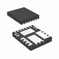
IR3831WMTR1PBF International Rectifier, IR3831WMTR1PBF Datasheet - Page 14

IR3831WMTR1PBF
Manufacturer Part Number
IR3831WMTR1PBF
Description
IC REG SYNC BUCK 8A 15-QFN
Manufacturer
International Rectifier
Series
SupIRBuck™r
Datasheet
1.IR3831WMTR1PBF.pdf
(32 pages)
Specifications of IR3831WMTR1PBF
Applications
Converter, DDR
Voltage - Input
1.5 ~ 16 V
Number Of Outputs
1
Voltage - Output
0.6 ~ 14.4 V
Operating Temperature
-40°C ~ 125°C
Mounting Type
Surface Mount
Package / Case
15-PowerVQFN
Part Status
Preferred
Package
PQFN / 5 x 6
Circuit
Single Output
Iout (a)
8
Switch Freq (khz)
250 - 1500
Input Range (v)
1.5 - 16
Output Range (v)
0.7 - 0.9*Vin
Ocp Otp Uvlo Pre-bias Soft Start And
PGOOD + EN + OVD + DDR Tracking
Server Storage
Yes
Routers Switches
Yes
Base Station Telecom
Yes
Lead Free Status / RoHS Status
Lead free / RoHS Compliant
Other names
IR3831WMTR1PBFTR
Operating Frequency
The switching frequency can be programmed
between 250kHz – 1500kHz by connecting an
external resistor from R
tabulates the oscillator frequency versus R
Shutdown
The IR3831W can be shutdown by pulling the
Enable pin below its 1 V threshold. This will tri-
state both, the high side driver as well as the low
side driver. Alternatively, the output
shutdown by pulling the soft-start pin below 0.3V.
Normal operation is resumed by cycling the
voltage at the Soft Start pin.
Over-Current Protection
The over current protection is performed by
sensing current through the R
MOSFET. This method enhances the converter’s
efficiency and reduces cost by eliminating a
current sense resistor. As shown in figure 7, an
external resistor (R
OCSet pin and the switch node (SW) which sets
the current limit set point.
Table 1. Switching Frequency and I
An internal current source sources current (I
) out of the OCSet pin. This current is a function
of the switching frequency and hence, of R
Rev 14.0
R
R
47.5
47.5
35.7
35.7
28.7
28.7
23.7
23.7
20.5
20.5
17.8
17.8
15.8
15.8
14.3
14.3
12.7
12.7
11.5
11.5
10.7
10.7
9.76
9.76
9.31
9.31
t
t
(kΩ)
(kΩ)
External Resistor (R
F
F
300
300
400
400
500
500
600
600
700
700
800
800
900
900
1000
1000
1100
1100
1200
1200
1300
1300
1400
1400
1500
1500
s
s
OCSet
(kHz)
(kHz)
t
) is connected between
pin to Gnd. Table 1
DS(on)
t
)
I
I
29.4
29.4
39.2
39.2
48.7
48.7
59.07
59.07
68.2
68.2
78.6
78.6
88.6
88.6
97.9
97.9
110.2
110.2
121.7
121.7
130.8
130.8
143.4
143.4
150.3
150.3
ocset
ocset
OCSet
of low side
(μA)
(μA)
t
vs.
can be
.
t
.
OCSet
An over current is detected if the OCSet pin goes
below ground. Hence, at the current limit
threshold, V
setting I
An
comparator, latches OCP signal and cycles the
soft start function in hiccup mode.
The hiccup is performed by shorting the soft-start
capacitor to ground and counting the number of
switching cycles. The Soft Start pin is held low
until 4096 cycles have been completed. The
OCP signal resets and the converter recovers.
After every soft start cycle, the converter stays in
this mode until the overload or short circuit is
removed.
The OCP circuit starts sampling current typically
160 ns after the low gate drive rises to about 3V.
This delay functions to filter out switching noise.
Fig. 7. Connection of over current sensing resistor
Table 1. shows I
frequencies.
develops a voltage across R
side MOSFET is turned on, the inductor current
flows through the Q2 and results in a voltage at
OCSet which is given by:
V
R
OCSet
OCSet
overcurrent
I
OCSet
Limit
=
=
, R
(
(
R
μA
I
OCset
OCSet
OCSet
DS
)
=
(
I
The
=0. Then, for a current limit
on
OCSet
IR3831WMPbF
∗
is calculated as follows:
R
)
detection
R
1400
*
t
OCSet
(k
OCSet
I
Ω
Limit
internal
)
..........
)
..........
−
at different switching
(
R
OCSet
trips
DS
..........
..........
(on
current
. When the low
)
∗
the
I
....
..........
L
)
(4)
..........
OCP
14
source
.....(
.(3)
) 2


