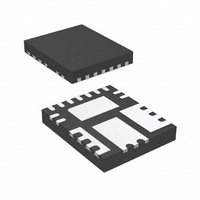
IR3831WMTR1PBF International Rectifier, IR3831WMTR1PBF Datasheet - Page 4

IR3831WMTR1PBF
Manufacturer Part Number
IR3831WMTR1PBF
Description
IC REG SYNC BUCK 8A 15-QFN
Manufacturer
International Rectifier
Series
SupIRBuck™r
Datasheet
1.IR3831WMTR1PBF.pdf
(32 pages)
Specifications of IR3831WMTR1PBF
Applications
Converter, DDR
Voltage - Input
1.5 ~ 16 V
Number Of Outputs
1
Voltage - Output
0.6 ~ 14.4 V
Operating Temperature
-40°C ~ 125°C
Mounting Type
Surface Mount
Package / Case
15-PowerVQFN
Part Status
Preferred
Package
PQFN / 5 x 6
Circuit
Single Output
Iout (a)
8
Switch Freq (khz)
250 - 1500
Input Range (v)
1.5 - 16
Output Range (v)
0.7 - 0.9*Vin
Ocp Otp Uvlo Pre-bias Soft Start And
PGOOD + EN + OVD + DDR Tracking
Server Storage
Yes
Routers Switches
Yes
Base Station Telecom
Yes
Lead Free Status / RoHS Status
Lead free / RoHS Compliant
Other names
IR3831WMTR1PBFTR
Pin Description
Pin
10
11
12
13
14
15
Rev 14.0
1
2
3
4
5
6
7
8
9
SS/SD
PGood
Enable
Name
OCSet
Comp
PGnd
Boot
Gnd
Gnd
V
SW
V
Vp
Fb
Rt
CC
IN
¯¯
Track pin. Use External resistors from VDDQ rail. The Vp voltage can
be set to 0.9V for DDR2 application and 0.75 or 0.6V for DDR3
application.
Inverting input to the error amplifier. This pin is connected directly to the
output of the regulator via resistor divider to set the output voltage and
provide feedback to the error amplifier.
Output of error amplifier. An external resistor and capacitor network is
typically connected from this pin to Fb pin to provide loop
compensation.
Signal ground for internal reference and control circuitry.
Set the switching frequency. Connect an external resistor from this pin
to Gnd to set the switching frequency.
Soft start / shutdown. This pin provides user programmable soft-start
function. Connect an external capacitor from this pin to Gnd to set the
start up time of the output voltage. The converter can be shutdown by
pulling this pin below 0.3V.
Current limit set point. A resistor from this pin to SW pin will set the
current limit threshold.
Power Good status pin. Output is open drain. Connect a pull up resistor
from this pin to Vcc. If unused, it can be left open.
This pin powers the internal IC and drivers. A minimum of 1uF high
frequency capacitor must be connected from this pin to the power
ground (PGnd).
Power Ground. This pin serves as a separated ground for the MOSFET
drivers and should be connected to the system’s power ground plane.
Switch node. This pin is connected to the output inductor.
Input voltage connection pin.
Supply voltage for high side driver. Connect a 0.1uF capacitor from this
pin to SW.
Enable pin to turn on and off the device.
Signal ground for internal reference and control circuitry.
Description
IR3831WMPbF
4


