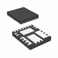
IR3831WMTR1PBF International Rectifier, IR3831WMTR1PBF Datasheet - Page 20

IR3831WMTR1PBF
Manufacturer Part Number
IR3831WMTR1PBF
Description
IC REG SYNC BUCK 8A 15-QFN
Manufacturer
International Rectifier
Series
SupIRBuck™r
Datasheet
1.IR3831WMTR1PBF.pdf
(32 pages)
Specifications of IR3831WMTR1PBF
Applications
Converter, DDR
Voltage - Input
1.5 ~ 16 V
Number Of Outputs
1
Voltage - Output
0.6 ~ 14.4 V
Operating Temperature
-40°C ~ 125°C
Mounting Type
Surface Mount
Package / Case
15-PowerVQFN
Part Status
Preferred
Package
PQFN / 5 x 6
Circuit
Single Output
Iout (a)
8
Switch Freq (khz)
250 - 1500
Input Range (v)
1.5 - 16
Output Range (v)
0.7 - 0.9*Vin
Ocp Otp Uvlo Pre-bias Soft Start And
PGOOD + EN + OVD + DDR Tracking
Server Storage
Yes
Routers Switches
Yes
Base Station Telecom
Yes
Lead Free Status / RoHS Status
Lead free / RoHS Compliant
Other names
IR3831WMTR1PBFTR
The transfer function (V
The (s) indicates that the transfer function varies
as a function of frequency. This configuration
introduces a gain and zero, expressed by:
First select the desired zero-crossover frequency
(F
Use the following equation to calculate R3:
Rev 14.0
o
R =
):
3
H(s) dB
F
H
z
F
V
( )
o
osc
Fig. 13. Type II compensation network
=
s
V
V
>
2
e
o
π
*
Z
=
F
V
F
=
IN
ESR
*
in
R
R
o
Gain(dB)
and its asymptotic gain plot
R
H
3
8
1
*
*
(
3
F
s
F
*
and
)
ESR
.........
LC
2
C
F
=
V
Z
4
−
OUT
*
F
Z
..........
Z
R
R
R
o
..........
IN
f
e
8
8
9
≤
/V
=
..........
(
V
1/5
o
−
Fb
..........
REF
) is given by:
..........
1
+
sR
~
sR
..........
1/10
8
C
R
........
3
E/A
.........
C
4
3
4
)
*
.......
F
C
F
.....
(20)
s
POLE
(19)
POLE
(18)
(21)
C
Comp
4
Frequency
Z
Ve
f
H
(
s
Where:
V
V
F
F
F
R
To cancel one of the LC filter poles, place the
zero before the LC filter resonant frequency pole:
Use equations (20), (21) and (22) to calculate
C4.
One more capacitor is sometimes added in
parallel with C4 and R3. This introduces one
more pole which is mainly used to suppress the
switching noise.
The additional pole is given by:
The pole sets to one half of the switching
frequency which results in the capacitor C
For a general solution for unconditional stability
for any type of output capacitors, and a wide
range of ESR values, we should implement local
feedback with a type III compensation network.
The typically used compensation network for
voltage-mode controller is shown in figure 14.
Again, the transfer function is given by:
By replacing Z
the transfer function can be expressed as:
C
)
o
ESR
LC
in
osc
8
=
F
F
POLE
= Crossover Frequency
F
= Feedback Resistor
= Maximum Input Voltage
z
z
−
= Resonant Frequency of the Output Filter
P
= Oscillator Ramp Voltage
=
=
sR
= Zero Frequency of the Output Capacitor
=
75
0
=
.
8
2
75
%
π
(
π
C
*R
*
F
*
4
LC
2
R
(
+
3
1
π
*F
3
+
C
V
V
1
*
in
s
sR
3
L
e
o
C
C
)
1
o
−
1
and Z
⎡
⎢
⎢
⎣
=
4
1
4
3
*
C
C
IR3831WMPbF
+
+
H
C
*
1
4
4
C
C
sR
o
(
)
s
POLE
[
POLE
≅
1
..........
)
f
3
+
=
π
according to figure 14,
⎛
⎜
⎜
⎝
sC
C
*R
C
−
4
4
Z
1
..........
Z
7
3
..........
+
*
*F
IN
(
f
R
C
C
s
8
3
3
..........
+
⎞
⎟
⎟
⎠
..........
⎤
⎥
⎥
⎦
..........
R
(
1
10
+
)
]
sR
..........
..........
.......
10
C
(22)
7
POLE
...(23)
)
.
....
.(24)
20
:
(25)


