L4901A STMicroelectronics, L4901A Datasheet
L4901A
Specifications of L4901A
Available stocks


Related parts for L4901A


L4901A Summary of contents
Page 1
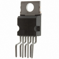
... RESET OUTPUT HIGH . OUTPUT TRANSISTORS SO A PROTECTION SHORT CIRCUIT AND THERMAL OVER- LOAD PROTECTION DESCRIPTION The L4901A is a monolithic low drop dual 5V regulator designed mainly for supplying microproc- essor systems. Reset and data save functions during switch on/off can be realized. PIN CONNECTION ...
Page 2
... L4901A PIN DESCRIPTION N Name 1 Input 1 Low Quiescent Current 400mA Regulator Input. 2 Input 2 400mA regulator input. 3 Timing If Reg switched-ON the delay capacitor is charged with constant current. When Reg. Capacitor 2 is switched-OFF the delay capacitor is decharged. 4 GND Common Ground. 5 Reset When pin 3 reaches 5V the reset output is switched high. ...
Page 3
... IN2 6.3V < V < 13V 500 –<0>5mA 10nF t = 10nF t – 125 C amb – 125 C amb f = 100Hz 0. 100mA L4901A Value 24 60 Internally Limited – 150 Value 4 Min. Typ. Max. 20 4.95 5.05 5.15 V –0 0.1 400 1 400 0.7 0.8 0.8 1 1.1 1 ...
Page 4
... The L4901A makes it very easy to supply such equip- ments ; it provides two voltage regulators (both 5 V high precision) with separate inputs plus a reset output for the data save function ...
Page 5
... Figure 2 shows an application circuit for a system typically used in trip computers or in car radios with programmable tuning. Reg permanently connected to a battery and supplies a CMOS time-of-day clock and a CMOS microcomputer chip with volatile memory. Reg. 2 may be switched OFF when the system is L4901A P 5/10 ...
Page 6
... L4901A inactive. Figure 4 shows the L4901A with a back up battery on the V output to maintain a CMOS time-of-day 01 clock and a stand by type N-MOS P . The reset output makes sure that the RAM is forced into the low consumption stand by state, so the access to memory is inhibit and the back up battery voltage ...
Page 7
... P and, through the address decoder M74HC138, to ensure that the RAMS are disabled as soon as the main supply starts to fall. Another interesting application of the L4901A system with shadow memories (see Figure 6). Figure 6 Figure 7 : Quiescent Current (reg.1) versus Output Current When the input voltage goes below V ouput enables the execution of a routine that saves the machine’ ...
Page 8
... L4901A Figure 9 : Total Quiescent Current versus Input Voltage Figure 11 : Regulator 1 Output Current and Short Circuit Current versus Input Voltage 8/10 Figure 10 : Regulator 1 Output Current and Short Circuit Current versus Input Voltage Figure 12 : Supply Voltage Rejection Regulators 1 and 2 versus Input Rip- ple Frequence ...
Page 9
... L4901A OUTLINE AND Heptawatt HEPTAMEC 9/10 ...
Page 10
... L4901A Information furnished is believed to be accurate and reliable. However, STMicroelectronics assumes no responsibility for the consequences of use of such information nor for any infringement of patents or other rights of third parties which may result from its use. No license is granted by implication or otherwise under any patent or patent rights of STMicroelectronics. Specification mentioned in this publication are subject to change without notice ...