L296 STMicroelectronics, L296 Datasheet - Page 2
L296
Manufacturer Part Number
L296
Description
IC REG SW HIGH CURR MULTIWATT15
Manufacturer
STMicroelectronics
Type
Step-Down (Buck)r
Datasheet
1.L296HT.pdf
(22 pages)
Specifications of L296
Internal Switch(s)
Yes
Synchronous Rectifier
No
Number Of Outputs
1
Voltage - Output
5.1 ~ 40 V
Current - Output
4A
Frequency - Switching
100kHz ~ 200kHz
Voltage - Input
9 ~ 46 V
Operating Temperature
-40°C ~ 150°C
Mounting Type
Through Hole
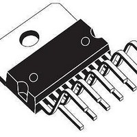
Package / Case
Multiwatt-15 (Vertical, Bent and Staggered Leads)
Power - Output
20W
Output Voltage
40 V
Output Current
4 A
Input Voltage
9 V to 46 V
Switching Frequency
200 KHz
Operating Temperature Range
- 40 C to + 150 C
Mounting Style
Through Hole
Duty Cycle (max)
100 %
Primary Input Voltage
40V
No. Of Outputs
1
No. Of Pins
15
Frequency
200GHz
Ic Generic Number
296
Rohs Compliant
Yes
Lead Free Status / RoHS Status
Lead free / RoHS Compliant
Other names
497-2939-5
Available stocks
Company
Part Number
Manufacturer
Quantity
Price

Part Number:
L296
Manufacturer:
ST
Quantity:
20 000
Part Number:
L296H
Manufacturer:
ST
Quantity:
20 000
Part Number:
L296HT
Manufacturer:
ST
Quantity:
20 000
Part Number:
L296P
Manufacturer:
ST
Quantity:
20 000
Company:
Part Number:
L296PHT
Manufacturer:
SHARP
Quantity:
4 528


PIN FUNCTIONS
L296 - L296P
BLOCK DIAGRAM
2/22
N
10
11
12
13
14
15
1
2
3
4
5
6
7
8
9
CROWBAR OUTPUT SCR gate drive output of the crowbar circuit.
SUPPLY VOLTAGE
FEEDBACK INPUT
CROWBAR INPUT
COMPENSATION
CURRENT LIMIT
RESET OUTPUT
RESET DELAY
INHIBIT INPUT
RESET INPUT
OSCILLATOR
SOFT START
FREQUENCY
SYNC INPUT
GROUND
OUTPUT
Name
Voltage Sense Input for Crowbar Overvoltage Protection. Normally connected to the
feedback input thus triggering the SCR when V
also monitor the input and a voltage divider can be added to increase the threshold.
Connected to ground when SCR not used.
Regulator Output
Unrergulated Voltage Input. An internal Regulator Powers the L296s Internal Logic.
A resistor connected between this terminal and ground sets the current limiter
threshold. If this terminal is left unconnected the threshold is internally set (see
electrical characteristics).
Soft Start Time Constant. A capacitor is connected between this terminal and ground
to define the soft start time constant. This capacitor also determines the average
short circuit output current.
TTL – Level Remote Inhibit. A logic high level on this input disables the device.
Multiple L296s are synchronized by connecting the pin 7 inputs together and omitting
the oscillator RC network on all but one device.
Common Ground Terminal
A series RC network connected between this terminal and ground determines the
regulation loop gain characteristics.
The Feedback Terminal on the Regulation Loop. The output is connected directly to
this terminal for 5.1V operation ; it is connected via a divider for higher voltages.
A parallel RC networki connected to this terminal determines the switching frequency.
This pin must be connected to pin 7 input when the internal oscillator is used.
Input of the Reset Circuit. The threshold is roughly 5 V. It may be connected to the
feedback point or via a divider to the input.
A capacitor connected between this terminal and ground determines the reset signal
delay time.
Open collector reset signal output. This output is high when the supply is safe.
Function
out
exceeds nominal by 20 %. May
Related parts for L296
Image
Part Number
Description
Manufacturer
Datasheet
Request
R

Part Number:
Description:
STMicroelectronics [RIPPLE-CARRY BINARY COUNTER/DIVIDERS]
Manufacturer:
STMicroelectronics
Datasheet:
Part Number:
Description:
STMicroelectronics [LIQUID-CRYSTAL DISPLAY DRIVERS]
Manufacturer:
STMicroelectronics
Datasheet:

Part Number:
Description:
BOARD EVAL FOR MEMS SENSORS
Manufacturer:
STMicroelectronics
Datasheet:
Part Number:
Description:
NPN TRANSISTOR POWER MODULE
Manufacturer:
STMicroelectronics
Datasheet:
Part Number:
Description:
TURBOSWITCH ULTRA-FAST HIGH VOLTAGE DIODE
Manufacturer:
STMicroelectronics
Datasheet:
Part Number:
Description:
Manufacturer:
STMicroelectronics
Datasheet:
Part Number:
Description:
DIODE / SCR MODULE
Manufacturer:
STMicroelectronics
Datasheet:
Part Number:
Description:
DIODE / SCR MODULE
Manufacturer:
STMicroelectronics
Datasheet:
Part Number:
Description:
Search -----> STE16N100
Manufacturer:
STMicroelectronics
Datasheet:
Part Number:
Description:
Search ---> STE53NA50
Manufacturer:
STMicroelectronics
Datasheet:
Part Number:
Description:
NPN Transistor Power Module
Manufacturer:
STMicroelectronics
Datasheet:
Part Number:
Description:
DIODE / SCR MODULE
Manufacturer:
STMicroelectronics
Datasheet: