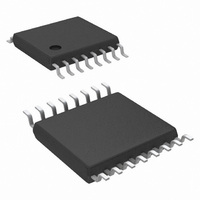
LM20145MHE/NOPB National Semiconductor, LM20145MHE/NOPB Datasheet - Page 11

LM20145MHE/NOPB
Manufacturer Part Number
LM20145MHE/NOPB
Description
IC REG SYNC BUCK 5A ADJ 16-TSSOP
Manufacturer
National Semiconductor
Series
PowerWise®r
Type
Step-Down (Buck)r
Datasheet
1.LM20145MHXNOPB.pdf
(22 pages)
Specifications of LM20145MHE/NOPB
Internal Switch(s)
Yes
Synchronous Rectifier
Yes
Number Of Outputs
1
Voltage - Output
0.8 ~ 5 V
Current - Output
5A
Frequency - Switching
250kHz ~ 750kHz
Voltage - Input
2.95 ~ 5.5 V
Operating Temperature
-40°C ~ 125°C
Mounting Type
Surface Mount
Package / Case
16-TSSOP Exposed Pad, 16-eTSSOP, 16-HTSSOP
Power - Output
2.6W
For Use With
LM20145EVAL - BOARD EVAL 5A POWERWISE LM20145
Lead Free Status / RoHS Status
Lead free / RoHS Compliant
Other names
LM20145MHE
Available stocks
Company
Part Number
Manufacturer
Quantity
Price
Company:
Part Number:
LM20145MHE/NOPB
Manufacturer:
NS
Quantity:
428
perature is exceeded. When activated, typically at 160°C, the
LM20145 tri-states the power FETs and resets soft start. After
the junction cools to approximately 150°C, the part starts up
using the normal start up routine. This feature is provided to
prevent catastrophic failures from accidental device over-
heating.
LIGHT LOAD OPERATION
The LM20145 offers increased efficiency when operating at
light loads. Whenever the load current is reduced to a point
where the peak to peak inductor ripple current is greater than
two times the load current, the part will enter the diode emu-
lation mode preventing significant negative inductor current.
The point at which this occurs is the critical conduction bound-
ary and can be calculated by the following equation:
FIGURE 1. Modes of Operation for LM20145
11
Several diagrams are shown in Figure 1 illustrating continu-
ous conduction mode (CCM), discontinuous conduction
mode, and the boundary condition.
It can be seen that in diode emulation mode, whenever the
inductor current reaches zero the SW node will become high
impedance. Ringing will occur on this pin as a result of the LC
tank circuit formed by the inductor and the parasitic capaci-
tance at the node. If this ringing is of concern an additional
RC snubber circuit can be added from the switch node to
ground.
At very light loads, usually below 100 mA, several pulses may
be skipped in between switching cycles, effectively reducing
the switching frequency and further improving light-load effi-
ciency.
30030705
www.national.com


