MT16HTF12864HY-667B3 Micron Technology Inc, MT16HTF12864HY-667B3 Datasheet - Page 14
MT16HTF12864HY-667B3
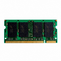
Manufacturer Part Number
MT16HTF12864HY-667B3
Description
MODULE DDR2 1GB 200-SODIMM
Manufacturer
Micron Technology Inc
Datasheet
1.MT16HTF12864HY-667B3.pdf
(15 pages)
Specifications of MT16HTF12864HY-667B3
Memory Type
DDR2 SDRAM
Memory Size
1GB
Speed
667MT/s
Package / Case
200-SODIMM
Main Category
DRAM Module
Sub-category
DDR2 SDRAM
Module Type
200SODIMM
Device Core Size
64b
Organization
128Mx64
Total Density
1GByte
Chip Density
512Mb
Access Time (max)
45ps
Maximum Clock Rate
667MHz
Operating Supply Voltage (typ)
1.8V
Operating Current
1.496A
Number Of Elements
16
Operating Supply Voltage (max)
1.9V
Operating Supply Voltage (min)
1.7V
Operating Temp Range
0C to 70C
Operating Temperature Classification
Commercial
Pin Count
200
Mounting
Socket
Lead Free Status / RoHS Status
Lead free / RoHS Compliant


Serial Presence-Detect
Table 11: SPD EEPROM Operating Conditions
Table 12: SPD EEPROM AC Operating Conditions
PDF: 09005aef818e4054
htf16c128_256x64h.pdf - Rev. D 3/10 EN
Parameter/Condition
Supply voltage
Input high voltage: logic 1; All inputs
Input low voltage: logic 0; All inputs
Output low voltage: I
Input leakage current: V
Output leakage current: V
Standby current
Power supply current, READ: SCL clock frequency = 100 kHz
Power supply current, WRITE: SCL clock frequency = 100 kHz
Parameter/Condition
SCL LOW to SDA data-out valid
Time bus must be free before a new transition can start
Data-out hold time
SDA and SCL fall time
SDA and SCL rise time
Data-in hold time
Start condition hold time
Clock HIGH period
Noise suppression time constant at SCL, SDA inputs
Clock LOW period
SCL clock frequency
Data-in setup time
Start condition setup time
Stop condition setup time
WRITE cycle time
OUT
Notes:
IN
= 3mA
OUT
= GND to V
For the latest SPD data, refer to Micron's SPD page: www.micron.com/SPD.
= GND to V
1. To avoid spurious start and stop conditions, a minimum delay is placed between SCL = 1
2. This parameter is sampled.
3. For a restart condition or following a WRITE cycle.
4. The SPD EEPROM WRITE cycle time (
and the falling or rising edge of SDA.
write sequence to the end of the EEPROM internal ERASE/PROGRAM cycle. During the
WRITE cycle, the EEPROM bus interface circuit is disabled, SDA remains HIGH due to pull-
up resistance, and the EEPROM does not respond to its slave address.
DD
DD
1GB, 2GB (x64, DR) 200-Pin DDR2 SDRAM SODIMM
14
t
Symbol
t
t
t
t
HD:DAT
HD:STA
SU:DAT
SU:STA
SU:STO
t
t
t
t
HIGH
LOW
WRC
t
t
t
BUF
Symbol
SCL
AA
DH
t
t
V
t
R
F
I
I
DDSPD
V
I
V
CCW
V
I
I
CCR
t
I
Micron Technology, Inc. reserves the right to change products or specifications without notice.
LO
SB
OL
LI
WRC) is the time from a valid stop condition of a
IH
IL
Min
200
100
0.2
1.3
0.6
0.6
1.3
0.6
0.6
V
–
–
0
–
–
–
DDSPD
Min
–0.6
0.05
1.7
0.1
1.6
0.4
–
2
× 0.7
Serial Presence-Detect
Max
300
300
400
0.9
50
10
–
–
–
–
–
–
–
–
–
© 2004 Micron Technology, Inc. All rights reserved.
V
V
DDSPD
DDSPD
Max
3.6
0.4
3
3
4
1
3
Units
+ 0.5
× 0.3
kHz
ms
µs
µs
ns
ns
ns
µs
µs
µs
µs
µs
ns
µs
µs
Units
Notes
mA
mA
µA
µA
µA
V
V
V
V
1
2
2
3
4
Related parts for MT16HTF12864HY-667B3
Image
Part Number
Description
Manufacturer
Datasheet
Request
R

Part Number:
Description:
IC SDRAM 64MBIT 133MHZ 54TSOP
Manufacturer:
Micron Technology Inc
Datasheet:

Part Number:
Description:
IC SDRAM 64MBIT 5.5NS 86TSOP
Manufacturer:
Micron Technology Inc
Datasheet:
Part Number:
Description:
IC SDRAM 64MBIT 200MHZ 86TSOP
Manufacturer:
Micron Technology Inc
Datasheet:
Part Number:
Description:
IC SDRAM 64MBIT 133MHZ 54TSOP
Manufacturer:
Micron Technology Inc
Datasheet:
Part Number:
Description:
IC SDRAM 128MBIT 133MHZ 54TSOP
Manufacturer:
Micron Technology Inc
Datasheet:

Part Number:
Description:
IC SDRAM 256MBIT 133MHZ 90VFBGA
Manufacturer:
Micron Technology Inc
Datasheet:
Part Number:
Description:
IC SDRAM 128MBIT 133MHZ 54TSOP
Manufacturer:
Micron Technology Inc
Datasheet:
Part Number:
Description:
IC SDRAM 256MBIT 133MHZ 54TSOP
Manufacturer:
Micron Technology Inc
Datasheet:

Part Number:
Description:
IC DDR SDRAM 512MBIT 6NS 66TSOP
Manufacturer:
Micron Technology Inc
Datasheet:
Part Number:
Description:
IC SDRAM 128MBIT 167MHZ 86TSOP
Manufacturer:
Micron Technology Inc
Datasheet:
Part Number:
Description:
IC SDRAM 128MBIT 143MHZ 86TSOP
Manufacturer:
Micron Technology Inc
Datasheet:

Part Number:
Description:
SDRAM 256M-BIT 1.8V 54-PIN VFBGA
Manufacturer:
Micron Technology Inc
Datasheet:
Part Number:
Description:
IC SDRAM 128MBIT 143MHZ 86TSOP
Manufacturer:
Micron Technology Inc
Datasheet:

Part Number:
Description:
IC SDRAM 128MBIT 125MHZ 54VFBGA
Manufacturer:
Micron Technology Inc
Datasheet:
Part Number:
Description:
IC SDRAM 128MBIT 125MHZ 54VFBGA
Manufacturer:
Micron Technology Inc
Datasheet: