PVG3A502A01R00 Murata Electronics North America, PVG3A502A01R00 Datasheet - Page 6
PVG3A502A01R00
Manufacturer Part Number
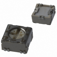
PVG3A502A01R00
Description
POT 5K OHM 3MM TRIM 1TRN SMD
Manufacturer
Murata Electronics North America
Series
PVG3r
Datasheet
1.PVG3A100A01R00.pdf
(8 pages)
Specifications of PVG3A502A01R00
Resistance (ohms)
5K
Power (watts)
0.25W, 1/4W
Taper
Linear
Tolerance
±20%
Temperature Coefficient
±150ppm/°C
Number Of Turns
Single
Adjustment Type
Top Adjustment
Mounting Type
Surface Mount
Resistive Material
Cermet
Package / Case
Square - 0.142" L x 0.134" W x 0.079" H (3.60mm x 3.40mm x 2.00mm)
Resistance In Ohms
5.00K
Lead Free Status / RoHS Status
Lead free / RoHS Compliant
Other names
490-2254-2
Available stocks
Company
Part Number
Manufacturer
Quantity
Price
Company:

Part Number:
PVG3A502A01R00
Manufacturer:
MOLEX
Quantity:
34 834


9
!Note
!Note
72
1
No.
The following describes trimmer potentiometer testing conducted by Murata Manufacturing Co., Ltd. in accordance with MIL-R-22097 (Military specification
for variable resistors, non-wirewound) and MIL-STD-202 (Test methods for electronic and electrical component parts).
SMD Sealed Type/Lead Sealed Type Specifications and Test Methods
1
2
3
4
5
Specifications and Test Methods
Total Resistance
Residual Resistance
Contact Resistance
Variation
Temperature Coefficient of
Resistance
Voltage Setting
Stability
• Please read rating and !CAUTION (for storage and operating, rating, soldering and mounting, handling) in this catalog to prevent smoking and/or burning, etc.
• This catalog has only typical specifications because there is no space for detailed specifications. Therefore, please approve our product specification or transact the approval sheet for product specification before ordering.
Please read rating and !CAUTION (for storage and operating, rating, soldering and mounting, handling) in this PDF catalog to prevent smoking and/or burning, etc.
This catalog has only typical specifications. Therefore, you are requested to approve our product specification or to transact the approval sheet for product specificaion before ordering.
Item
Measure total resistance between the resistance element and terminals (#1 and #3) with the contact arm positioned
against a stop. The positioning of the contact arm and terminal shall be the same for subsequent total resistance
measurements on the same device. Use the test voltage specified in Table-1 for total resistance measurements.
This voltage shall be used for all subsequent total resistance measurements.
Position the contact arm at the extreme counterclockwise limit of mechanical travel and measure the resistance
between the contact arm and the corresponding end terminal. Then, position the contact arm at the extreme clock-
wise limit of mechanical travel and measure the resistance between the contact arm and the corresponding end ter-
minal. During this test, take suitable precautions to ensure that the rated current of the resistance element is not
exceeded.
Contact resistance variation shall be measured with the measuring circuit shown in Figure-1, or its equivalent. The
adjustment rotor (screw) shall be rotated in both directions through 90% of the actual effective-electrical rotational
angle(number of turns) for a total of 6 cycles. Only the last 3 cycles shall count in determining whether or not a con-
tact resistance variation is observed at least twice in the same location, exclusive of the roll-on or roll-off points
where the contact arm moves from the termination, on or off, the resistance element. The rate of rotation of the
adjustment rotor (screw) shall be such that the adjustment rotor (screw) completes 1 cycle for 5 seconds minimum to
2 minutes maximum. The test current used shall follow the value given in Table-2 unless otherwise limited by power
rating.
The trimmer potentiometer shall be subjected to the following each temperature (see Table-3) for 30-45 minutes.
Temperature coefficient of resistance shall be applied to the following formula.
TCR=
Note) * : Reference temperature
The wiper shall be set at approximately 40% of the actual effective-electrical rotational angle (number of turns). An
adequate DC test potential shall be applied between the terminal #1 and the terminal #3. The voltage between the
terminal #1 and the terminal #3, and the voltage between the terminal #1 and the terminal #2, shall be measured
and applied to the following formula.
Voltage setting stability=
e : Before test
e': After test
E : The voltage between the terminal #1 and the terminal #3
Total resistance,
Standard total resistance
Temperature(°C)
(The voltage between the terminal #1 and the terminal #2)
(The voltage between the terminal #1 and the terminal #2)
100kFR
Nominal (ohm)
Table-1 Total resistance test voltage
100FRV1k
10kFRV100k
10VRV100
Sequence
1kFRV10k
200kVRF1M
R
T
T
R
R
100FRF500
500VRF1k
50kVRF200k
1MVRF2M
2MVR
1
Table-2 Test current for CRV
R
1
2
1kVRF2k
2kVRF50k
1
2
(T
R (ohm)
2
: Reference temperature in degrees celsius
: Test temperature in degrees celsius
: Resistance at reference temperature ohm
: Resistance at test temperature in ohm
– R
2
RV100
– T
1
1
)
Z 10
+25
(
Maximum Test
1*
6
e'
E
Voltage (V)
(ppm/°C)
–
100.0
10.0
30.0
E
e
1.0
3.0
Table-3 Test temperatures
Test current
)
-15
2
Z100 (%)
200µA
100µA
20mA
10mA
50µA
30µA
4mA
2mA
1mA
Min. operating
temperature
3
Test Methods
Constant Current Source not to
Exceed Rating of Unit Being
+25
4*
#1
+65
Rx : Trimmer Potentiometer
Oscilloscope bandwidth :100Hz to 50kHz
5
Figure-1 CRV measuring circuit
Max. operating
temperature
#1
e
Proofreaded
Resistance
#2
6
Figure-2
Rx
Continued on the following page.
E
#3
#2
R50E12.pdf 02.9.5
AC
Amplifier
#3
Oscilloscope
Related parts for PVG3A502A01R00
Image
Part Number
Description
Manufacturer
Datasheet
Request
R

Part Number:
Description:
BUZZER PIEZO 25VP-P SMD
Manufacturer:
Murata Electronics North America

Part Number:
Description:
CAP 4-ARRAY 680PF 100V X7R 1206
Manufacturer:
Murata Electronics North America
Datasheet:
Part Number:
Description:
CAP 4-ARRAY 1000PF 100V X7R 1206
Manufacturer:
Murata Electronics North America
Datasheet:
Part Number:
Description:
CAP 4-ARRAY 1800PF 100V X7R 1206
Manufacturer:
Murata Electronics North America
Datasheet:
Part Number:
Description:
CAP 4-ARRAY 68000PF 16V X7R 1206
Manufacturer:
Murata Electronics North America
Datasheet:

Part Number:
Description:
CAP CER 1000PF 50V 10% X7R 0402
Manufacturer:
Murata Electronics North America
Datasheet:
Part Number:
Description:
CAP CER 10000PF 16V 10% X7R 0402
Manufacturer:
Murata Electronics North America
Datasheet:

Part Number:
Description:
CAP 5.5-25PF 2.5X3.2MM SMD
Manufacturer:
Murata Electronics North America
Datasheet:

Part Number:
Description:
CAP 4.5-20PF 2.5X3.2MM SMD
Manufacturer:
Murata Electronics North America
Datasheet:

Part Number:
Description:
CAP 5.0-20PF 3.2X4.5MM SMD RED
Manufacturer:
Murata Electronics North America
Datasheet:

Part Number:
Description:
CAP 2.0-6.0PF 3.2X4.5MM SMD BLU
Manufacturer:
Murata Electronics North America
Datasheet:

Part Number:
Description:
CAP 1.4-3.0PF 3.2X4.5MM SMD BRN
Manufacturer:
Murata Electronics North America
Datasheet:

Part Number:
Description:
CAP 3.0-10PF 3.2X4.5MM SMD WHT
Manufacturer:
Murata Electronics North America
Datasheet:

Part Number:
Description:
CAP 2.0-6.0PF 4X4.5MM TOPADJ BLU
Manufacturer:
Murata Electronics North America
Datasheet:

Part Number:
Description:
CAP 8.5-40PF 4X4.5MM TOPADJ YEL
Manufacturer:
Murata Electronics North America
Datasheet: