PVG3A502A01R00 Murata Electronics North America, PVG3A502A01R00 Datasheet - Page 7
PVG3A502A01R00
Manufacturer Part Number
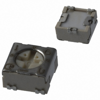
PVG3A502A01R00
Description
POT 5K OHM 3MM TRIM 1TRN SMD
Manufacturer
Murata Electronics North America
Series
PVG3r
Datasheet
1.PVG3A100A01R00.pdf
(8 pages)
Specifications of PVG3A502A01R00
Resistance (ohms)
5K
Power (watts)
0.25W, 1/4W
Taper
Linear
Tolerance
±20%
Temperature Coefficient
±150ppm/°C
Number Of Turns
Single
Adjustment Type
Top Adjustment
Mounting Type
Surface Mount
Resistive Material
Cermet
Package / Case
Square - 0.142" L x 0.134" W x 0.079" H (3.60mm x 3.40mm x 2.00mm)
Resistance In Ohms
5.00K
Lead Free Status / RoHS Status
Lead free / RoHS Compliant
Other names
490-2254-2
Available stocks
Company
Part Number
Manufacturer
Quantity
Price
Company:

Part Number:
PVG3A502A01R00
Manufacturer:
MOLEX
Quantity:
34 834


!Note
!Note
1
No.
10
11
12
6
7
8
9
Specifications and Test Methods
Continued from the preceding page.
Temperature Cycle
Humidity
Vibration
Shock
Temperature Road Life
High Temperature Exposure
(Except for PVF2)
Low Temperature Exposure
(Except for PVF2 and
PVM4A---B01)
• Please read rating and !CAUTION (for storage and operating, rating, soldering and mounting, handling) in this catalog to prevent smoking and/or burning, etc.
• This catalog has only typical specifications because there is no space for detailed specifications. Therefore, please approve our product specification or transact the approval sheet for product specification before ordering.
Please read rating and !CAUTION (for storage and operating, rating, soldering and mounting, handling) in this PDF catalog to prevent smoking and/or burning, etc.
This catalog has only typical specifications. Therefore, you are requested to approve our product specification or to transact the approval sheet for product specificaion before ordering.
Item
SMD Sealed Type/Lead Sealed Type Specifications and Test Methods
The trimmer potentiometer shall be subjected to Table-4 temperature for 5 cycles. The trimmer potentiometer shall
be removed from the chamber, and maintained at a temperature of 25±5°C for 1~2 hours.
1) PVC6, PV12, PV32, PV34 PVM4A---B01series
The trimmer potentiometer shall be placed in a chamber at a temperature of 40±2°C and a humidity of 90~95% with-
out loading for 250±8 hours. The trimmer potentiometer shall be removed from the chamber, and maintained at a
temperature of 25±5°C for 5±1/6 hours.
2) PVF2series
The trimmer potentiometer shall be placed in a chamber at 60±2°C and 90~95% without loading for 1000±12 hours.
The trimmer potentiometer shall be removed from the chamber, and maintained at a temperature of 25±5°C for
5±1/6 hours
2) PVG3, PVG5, PV01, PV22, PV23, PV36, PV37series
The trimmer potentiometer shall be subjected Figure-3 the programmed humidity environment for 10 cycle. The trim-
mer potentiometer shall be removed from the chamber, and maintained at a temperature of 25±5°C for 5±1/2 hours.
1) PV-- series
The trimmer potentiometer shall be vibrated throughout the frequency range at the 20G level. A complete frequency
range, 10Hz to 2000Hz and back, shall be made within 15 minutes for a total of 4 sweeps in each of the three axis
direction for a total of 12 sweeps.
2) PVF2 series
The trimmer potentiometer shall be subjected to vibration at 0.3 inch amplitude. The frequency shall be varied uni-
formly between the approximate limits of 10 Hz and 55Hz. This motion shall be applied for preiod of 2 hours in each
of 3 mutually perpendicular direction (total of 6 hours).
1) PV-- series
The trimmer potentiometer shall be shocked at the 100G (50G for PV22 and PV23series) level and shall be subject-
ed to 4 shocks in each of the three axis direction for a total of 12 shocks.
2) PVM4A---B01series
The trimmer potentiometer shall be shocked at the 100G level and shall be subjected to 3 shocks in each of the six
axis direction for a total of 18 shocks.
Full rated continuous working voltage not exceeding the maximum rated voltage shall be applied intermittently
between the terminal #1 and the terminal #3 of the trimmer potentiometer, 1.5 hours on and 0.5 hours off, for a total
of 1000±12 hours, at a temperature of 70±2°C (85±2°C for PV01 and PV37series, 50±2°C for PVF2series). The trim-
mer potentiometer shall be removed from the chamber, and maintained at a temperature of 25±5°C for 1 to 2 hours.
The trimmer potentiometer shall be placed in a camber at a temperature of 125±3°C (150±3°C for PV12series)
250±8 hours without loading. The trimmer potentiometer shall be removed from the camber, and maintained at a
temperature of 25±5°C for 1 to 2 hours.
The trimmer potentiometer shall be placed in a camber at a temperature of -55±3°C for 1 hours without loading. Full
rated continuous working voltage not exceeding the maximum rated voltage shall be applied for 45 minutes. The
trimmer potentiometer shall be removed from the chamber, and maintained at a temperature of 25±5°C for approxi-
mately 24 hours.
Temp.
(°C)
Time (min.)
Sequence
-10
70
65
60
55
50
45
40
35
30
25
20
15
10
-5
Table-4 One cycle of temperature cycle.
5
0
PV-- series
PVF2 series
PV22 series
HUMIDITY
UNCONTROLLED
INITIAL CONDITIONING
IN A DRY OVEN
INITIAL MEASUREMENTS
AS SPECIFIED IN 3.2
UNLESS OTHERWISE SPECIFIED
TEMPERATURE TOLERANCE IS,
CHAMBER EXCEPT THE IMMEDIATE
VICINITY OF THE SPECIMENS AND
THE CHAMBER SURFACES
2 C AT ALL POINTS WITHIN THE
SPECIFIED
PRIOR TO FIRST CYCLE
UNLESS OTHERWISE
24 HOURS
-55±3
-25±3
30
1
0
5 max.
+25±2
STEP 1
1
2
90-98%RH
RATE OF CHANGE OF TEMPERATURE IS UNSPECIFIED.
HOWEVER, SPECIMENS SHALL NOT BE SUBJECTED TO
RADIANT HEAT FROM CHAMBER-CONDITIONING
PROCESSES
2
VOLTAGE APPLIED AS SPECIFIED IN 3.5
3
STEP 2
+125±3
+150±3
+60±3
CIRCULATION OF CONDITIONING AIR SHALL
BE AT A MINIMUM CUBIC RATE PER MINUTE
EQUIVALENT TO 5 TIMES THE VOLUME OF
THE CHAMBER
4
30
3
5
STEPS 7a AND 7b PERFORMED DURING ANY
5 OF THE FIRST 9 CYCLES. HUMIDITY
UNCONTROLLED DURING STEPS 7a AND 7b
ONLY
80-98%RH
ONE CYCLE 24 HOURS. REPEAT AS SPECIFIED IN 3.3
STEP 3
Figure-3
6
5 max.
+25±2
7
Test Methods
4
8
STEP 4
+10 C
9
-2 C
90-98%RH
10
11
STEP 5
12
13
80-98%RH
14
STEP 6
15
16
17
MIL-STD-202 METHOD 106
18
STEP 7a
END OF FINAL CYCLE
MEASUREMENTS AS
SPECIFIED IN 3.6
90-98%RH
19
STEP 7
Continued on the following page.
20
21
22 23 24
STEP 7b
R50E12.pdf 02.9.5
73
9
Related parts for PVG3A502A01R00
Image
Part Number
Description
Manufacturer
Datasheet
Request
R

Part Number:
Description:
BUZZER PIEZO 25VP-P SMD
Manufacturer:
Murata Electronics North America

Part Number:
Description:
CAP 4-ARRAY 680PF 100V X7R 1206
Manufacturer:
Murata Electronics North America
Datasheet:
Part Number:
Description:
CAP 4-ARRAY 1000PF 100V X7R 1206
Manufacturer:
Murata Electronics North America
Datasheet:
Part Number:
Description:
CAP 4-ARRAY 1800PF 100V X7R 1206
Manufacturer:
Murata Electronics North America
Datasheet:
Part Number:
Description:
CAP 4-ARRAY 68000PF 16V X7R 1206
Manufacturer:
Murata Electronics North America
Datasheet:

Part Number:
Description:
CAP CER 1000PF 50V 10% X7R 0402
Manufacturer:
Murata Electronics North America
Datasheet:
Part Number:
Description:
CAP CER 10000PF 16V 10% X7R 0402
Manufacturer:
Murata Electronics North America
Datasheet:

Part Number:
Description:
CAP 5.5-25PF 2.5X3.2MM SMD
Manufacturer:
Murata Electronics North America
Datasheet:

Part Number:
Description:
CAP 4.5-20PF 2.5X3.2MM SMD
Manufacturer:
Murata Electronics North America
Datasheet:

Part Number:
Description:
CAP 5.0-20PF 3.2X4.5MM SMD RED
Manufacturer:
Murata Electronics North America
Datasheet:

Part Number:
Description:
CAP 2.0-6.0PF 3.2X4.5MM SMD BLU
Manufacturer:
Murata Electronics North America
Datasheet:

Part Number:
Description:
CAP 1.4-3.0PF 3.2X4.5MM SMD BRN
Manufacturer:
Murata Electronics North America
Datasheet:

Part Number:
Description:
CAP 3.0-10PF 3.2X4.5MM SMD WHT
Manufacturer:
Murata Electronics North America
Datasheet:

Part Number:
Description:
CAP 2.0-6.0PF 4X4.5MM TOPADJ BLU
Manufacturer:
Murata Electronics North America
Datasheet:

Part Number:
Description:
CAP 8.5-40PF 4X4.5MM TOPADJ YEL
Manufacturer:
Murata Electronics North America
Datasheet: