LSM2-T/6-W3-C Murata Power Solutions Inc, LSM2-T/6-W3-C Datasheet - Page 13
LSM2-T/6-W3-C
Manufacturer Part Number
LSM2-T/6-W3-C
Description
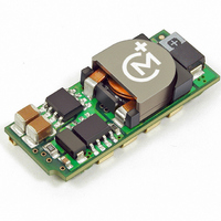
CONV DC/DC 19.8W 6A 5V SMD
Manufacturer
Murata Power Solutions Inc
Series
LSM2r
Type
Point of Load (POL) Non-Isolatedr
Datasheet
1.LSM2-T6-W3N-C.pdf
(17 pages)
Specifications of LSM2-T/6-W3-C
Output
0.75 ~ 3.3V
Number Of Outputs
1
Power (watts)
19W
Mounting Type
Surface Mount
Voltage - Input
2.4 ~ 5.5V
Package / Case
8-DIP SMD Module
1st Output
0.75 ~ 3.3 VDC @ 6A
Size / Dimension
1.30" L x 0.53" W x 0.34" H (33mm x 13.5mm x 8.6mm)
Power (watts) - Rated
19.8W
Operating Temperature
-40°C ~ 85°C
Efficiency
95.5%
Approvals
CSA, cUL, EN, UL
Dc / Dc Converter O/p Type
Variable
No. Of Outputs
1
Input Voltage
2.4V To 5.5V
Power Rating
19.8W
Output Voltage
3.3V
Output Current
6A
Approval Bodies
UL, CSA
Supply Voltage
5V
Product
Non-Isolated / POL
Output Power
20 W
Input Voltage Range
2.4 V to 5.5 V
Output Voltage (channel 1)
0.75 V to 3.3 V
Output Current (channel 1)
6 A
Lead Free Status / RoHS Status
Lead free / RoHS Compliant
3rd Output
-
2nd Output
-
Lead Free Status / Rohs Status
Lead free / RoHS Compliant
Other names
811-1781-2


Power Phasing Architectures
Observe the simplifi ed timing diagrams below. There are many possible power
phasing architectures and these are just some examples to help you analyze
your system. Each application will be different. Multiple output voltages may
require more complex timing than that shown here.
typical power output voltages. Generally the Master will be a primary power
voltage in the system which must be present fi rst or coincident with any
Slave power voltages. The Master output voltage is connected to the Slave’s
Sequence input, either by a voltage divider, divider-plus-capacitor or some
other method. Several standard sequencing architectures are prevalent. They
are concerned with three factors:
difference relationship is important for systems very concerned about possible
latchup of programmable devices or overdriving ESD diodes. Lower slew rates
avoid overcurrent shutdown during bypass cap charge-up.
different respective fi nal set point voltages. During the ramp, their voltages
are nearly identical. This avoids problems with large currents fl owing between
logic systems which are not initialized yet. Since both end voltages are differ-
ent, each converter reaches it’s setpoint voltage at a different time.
ing fi nal voltages at about the same time.
These diagrams illustrate the time and slew rate relationship between two
For most systems, the time relationship is the dominant factor. The voltage
In Figure 10, two POL’s ramp up at the same rate until they reach their
Figure 11 shows two POL’s with different slew rates in order to reach differ-
„
„
„
Figure 10. Coincident or Simultaneous Phasing (Identical Slew Rates)
The time relationship between the Master and Slave voltages
The voltage difference relationship between the Master and Slave
The voltage slew rate (ramp slope) of each converter’s output.
www.murata-ps.com
for two converters. Figure 12 is called “Inclusive” because the later starting
POL fi nishes inside the earlier POL. The timing in Figure 12 is more easily built
using a combined digital sequence controller and the Sequence/Track pin.
relationship staggered approximately the same at power-up and power-down.
Figures 12 and 13 show both delayed start up and delayed fi nal voltages
Figure 13 is the same strategy as Figure 12 but with an “exclusive” timing
Figure 12. Staggered or Sequential Phasing—Inclusive (Fixed Delays)
Figure 11. Proportional or Ratiometric Phasing (Identical V
Figure 13. Staggered or Sequential Phasing—Exclusive
Selectable-Output POL DC/DC Converters
25 Jun 2010
(Fixed Cascaded Delays)
Single Output, Non-Isolated
MDC_LSM2
LSM2 Series
email: sales@murata-ps.com
Series.B09Δ
OUT
Time)
Page 13 of 17
Related parts for LSM2-T/6-W3-C
Image
Part Number
Description
Manufacturer
Datasheet
Request
R

Part Number:
Description:
CONV DC/DC 19.8W 6A 5V SMD
Manufacturer:
Murata Power Solutions Inc
Datasheet:
Part Number:
Description:
CONV DC/DC 30W 6A 12V SMD
Manufacturer:
Murata Power Solutions Inc
Datasheet:
Part Number:
Description:
CONV DC/DC 30W 6A 12V SMD
Manufacturer:
Murata Power Solutions Inc
Datasheet:

Part Number:
Description:
DC/DC Converter
Manufacturer:
Murata Power Solutions Inc
Datasheet:
Part Number:
Description:
DC/DC Converter
Manufacturer:
Murata Power Solutions Inc
Datasheet:
Part Number:
Description:
DC/DC Converter
Manufacturer:
Murata Power Solutions Inc
Datasheet:
Part Number:
Description:
DC/DC Converter
Manufacturer:
Murata Power Solutions Inc
Datasheet:

Part Number:
Description:
CONV DC/DC 125W 30A 12V SMD
Manufacturer:
Murata Power Solutions Inc
Datasheet:
Part Number:
Description:
CONV DC/DC 125W 30A 12V SMD
Manufacturer:
Murata Power Solutions Inc
Datasheet:
Part Number:
Description:
CONV DC/DC 33W 10A 5V SMD
Manufacturer:
Murata Power Solutions Inc
Datasheet:

Part Number:
Description:
DC/DC Converter
Manufacturer:
Murata Power Solutions Inc
Datasheet:

Part Number:
Description:
Transformers 5Vin 5Vout 200mA 4000Vdc 1:1.33 turn
Manufacturer:
Murata Power Solutions Inc
Datasheet:

Part Number:
Description:
POWER SUPPLY
Manufacturer:
Murata Power Solutions Inc
Datasheet:

Part Number:
Description:
DPM LED MINI 2VDC 3.5DIG LP RED
Manufacturer:
Murata Power Solutions Inc
Datasheet:

Part Number:
Description:
CONV DC/DC 1W 5VIN 5VOUT SIP SGL
Manufacturer:
Murata Power Solutions Inc
Datasheet: