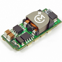
LSM2-T/6-W3-C Murata Power Solutions Inc, LSM2-T/6-W3-C Datasheet - Page 6

LSM2-T/6-W3-C
Manufacturer Part Number
LSM2-T/6-W3-C
Description
CONV DC/DC 19.8W 6A 5V SMD
Manufacturer
Murata Power Solutions Inc
Series
LSM2r
Type
Point of Load (POL) Non-Isolatedr
Datasheet
1.LSM2-T6-W3N-C.pdf
(17 pages)
Specifications of LSM2-T/6-W3-C
Output
0.75 ~ 3.3V
Number Of Outputs
1
Power (watts)
19W
Mounting Type
Surface Mount
Voltage - Input
2.4 ~ 5.5V
Package / Case
8-DIP SMD Module
1st Output
0.75 ~ 3.3 VDC @ 6A
Size / Dimension
1.30" L x 0.53" W x 0.34" H (33mm x 13.5mm x 8.6mm)
Power (watts) - Rated
19.8W
Operating Temperature
-40°C ~ 85°C
Efficiency
95.5%
Approvals
CSA, cUL, EN, UL
Dc / Dc Converter O/p Type
Variable
No. Of Outputs
1
Input Voltage
2.4V To 5.5V
Power Rating
19.8W
Output Voltage
3.3V
Output Current
6A
Approval Bodies
UL, CSA
Supply Voltage
5V
Product
Non-Isolated / POL
Output Power
20 W
Input Voltage Range
2.4 V to 5.5 V
Output Voltage (channel 1)
0.75 V to 3.3 V
Output Current (channel 1)
6 A
Lead Free Status / RoHS Status
Lead free / RoHS Compliant
3rd Output
-
2nd Output
-
Lead Free Status / Rohs Status
Lead free / RoHS Compliant
Other names
811-1781-2
is applied to the converter can cause permanent damage to the converter. The
on/off control function, however, is designed such that the converter can be
disabled (control pin pulled low) while input voltage is ramping up and then
"released" once the input has stabilized (see also power-up sequencing).
Power-up sequencing
If a controlled start-up of one or more LSM2 Series DC/DC converters is
required, or if several output voltages need to be powered-up in a given
sequence, the On/Off control pin can be driven with an external open collector
device as per Figure 4.
output of the DC/DC converter disabled. When the input to the external open
collector is pulled high, the DC/DC converter’s output will be enabled.
Output Overvoltage Protection
LSM2 SMT Series DC/DC converters do not incorporate output overvoltage
protection. In the extremely rare situation in which the device’s feedback loop
is broken, the output voltage may run to excessively high levels (V
is absolutely imperative that you protect your load against any and all possible
overvoltage situations, voltage limiting circuitry must be provided external to
the power converter.
Output Overcurrent Detection
Overloading the power converter's output for an extended time will invariably
cause internal component temperatures to exceed their maximum ratings and
eventually lead to component failure. High-current-carrying components such
as inductors, FET's and diodes are at the highest risk. LSM2 SMT Series DC/DC
converters incorporate an output overcurrent detection and shutdown function
that serves to protect both the power converter and its load.
output voltage drops to less than 98% of it original value, the LSM2's internal
overcurrent-detection circuitry immediately turns off the converter, which then
goes into a "hiccup" mode. While hiccupping, the converter will continuously
attempt to restart itself, go into overcurrent, and then shut down. Once the
output short is removed, the converter will automatically restart itself.
Applying an external voltage to the On/Off Control pin when no input power
Leaving the input of the on/off circuit closed during power-up will have the
If the output current exceeds it maximum rating by typically 50% or if the
Figure 4. On/Off Control Using An External Open Collector Driver
www.murata-ps.com
OUT
= V
IN
). If it
Output Reverse Conduction
Many DC/DCs using synchronous rectifi cation suffer from Output Reverse
Conduction. If those devices have a voltage applied across their output before a
voltage is applied to their input (this typically occurs when another power sup-
ply starts before them in a power-sequenced application), they will either fail to
start or self destruct. In both cases, the cause is the "freewheeling" or "catch"
FET biasing itself on and effectively becoming a short circuit.
tion. They employ proprietary gate drive circuitry that makes them immune to
moderate applied output overvoltages.
Thermal Considerations and Thermal Protection
The typical output-current thermal-derating curves shown below enable
designers to determine how much current they can reliably derive from each
model of the LSM2 SMT's under known ambient-temperature and air-fl ow
conditions. Similarly, the curves indicate how much air fl ow is required to reli-
ably deliver a specifi c output current at known temperatures.
whose heat is generated primarily by I
veloped using thermocouples to monitor the inductor temperature and varying
the load to keep that temperature below +110°C under the assorted condi-
tions of air fl ow and air temperature. Once the temperature exceeds +115°C
(approx.), the thermal protection will disable the converter. Automatic restart
occurs after the temperature has dropped below +110°C.
curves on the following pages, LSM2 SMT's maintain virtually constant
effi ciency from half to full load, and consequently deliver very impressive
temperature performance even if operating at full load.
subject to numerous factors and tolerances not taken into account here. If you
are attempting to extract the most current out of these units under demanding
temperature conditions, we advise you to monitor the output-inductor tempera-
ture to ensure it remains below +110°C at all times.
LSM2 SMT DC/DC converters do not suffer from Output Reverse Conduc-
The highest temperatures in LSM2 SMT's occur at their output inductor,
As you may deduce from the derating curves and observe in the effi ciency
Lastly, when LSM2 SMT's are installed in system boards, they are obviously
Selectable-Output POL DC/DC Converters
Figure 5. Inverting On/Off Control
25 Jun 2010
2
R losses. The derating curves were de-
Single Output, Non-Isolated
MDC_LSM2
LSM2 Series
email: sales@murata-ps.com
Series.B09Δ
Page 6 of 17


