LSM2-T/6-W3-C Murata Power Solutions Inc, LSM2-T/6-W3-C Datasheet - Page 4
LSM2-T/6-W3-C
Manufacturer Part Number
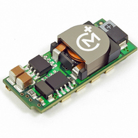
LSM2-T/6-W3-C
Description
CONV DC/DC 19.8W 6A 5V SMD
Manufacturer
Murata Power Solutions Inc
Series
LSM2r
Type
Point of Load (POL) Non-Isolatedr
Datasheet
1.LSM2-T6-W3N-C.pdf
(17 pages)
Specifications of LSM2-T/6-W3-C
Output
0.75 ~ 3.3V
Number Of Outputs
1
Power (watts)
19W
Mounting Type
Surface Mount
Voltage - Input
2.4 ~ 5.5V
Package / Case
8-DIP SMD Module
1st Output
0.75 ~ 3.3 VDC @ 6A
Size / Dimension
1.30" L x 0.53" W x 0.34" H (33mm x 13.5mm x 8.6mm)
Power (watts) - Rated
19.8W
Operating Temperature
-40°C ~ 85°C
Efficiency
95.5%
Approvals
CSA, cUL, EN, UL
Dc / Dc Converter O/p Type
Variable
No. Of Outputs
1
Input Voltage
2.4V To 5.5V
Power Rating
19.8W
Output Voltage
3.3V
Output Current
6A
Approval Bodies
UL, CSA
Supply Voltage
5V
Product
Non-Isolated / POL
Output Power
20 W
Input Voltage Range
2.4 V to 5.5 V
Output Voltage (channel 1)
0.75 V to 3.3 V
Output Current (channel 1)
6 A
Lead Free Status / RoHS Status
Lead free / RoHS Compliant
3rd Output
-
2nd Output
-
Lead Free Status / Rohs Status
Lead free / RoHS Compliant
Other names
811-1781-2


Performance/Functional Specifi cation Notes:
(1)
(2)
(3)
(4)
(5)
(6)
(7)
I/O Filtering and Noise Reduction
All models in the LSM2 Series are tested and specifi ed with external 1 || 10μF
ceramic/tantalum output capacitors and a 22μF tantalum input capacitor. These
capacitors are necessary to accommodate our test equipment and may not be
required to achieve desired performance in your application. The LSM2s are
designed with high-quality, high-performance internal I/O caps, and will oper-
ate within spec in most applications with no additional external components.
are fully rated to handle the units' input ripple currents. Similarly, the internal
output capacitors are specifi ed for low ESR and full-range frequency response.
fi ltering techniques, the simplest being the installation of external I/O caps.
minimize high-frequency variations in input voltage (usually caused by IR drops
in conductors leading to the DC/DC) as the switching converter draws pulses of
current. Input capacitors should be selected for bulk capacitance (at appropri-
ate frequencies), low ESR, and high rms-ripple-current ratings. The switching
nature of modern DC/DCs requires that the dc input voltage source have low ac
impedance at the frequencies of interest. Highly inductive source impedances
can greatly affect system stability. Your specifi c system confi guration may
necessitate additional considerations.
PARD) may be reduced below specifi ed limits with the installation of additional
external output capacitors. Output capacitors function as true fi lter elements
and should be selected for bulk capacitance, low ESR, and appropriate fre-
quency response. Any scope measurements of PARD should be made directly
In particular, the LSM2’s input capacitors are specifi ed for low ESR and
In critical applications, input/output ripple/noise may be further reduced using
External input capacitors serve primarily as energy-storage devices. They
Output ripple/noise (also referred to as periodic and random deviations or
All models are tested and specifi ed with external 1 || 10μF ceramic/tantalum output capaci-
tors and a 22μF external input capacitor. All capacitors are low ESR types. These capacitors are
necessary to accommodate our test equipment and may not be required to achieve specifi ed
performance in your applications. All models are stable and regulate within spec under no-load
conditions.
General conditions for Specifi cations are +25°C, V
nal” output voltage is +5V for D12 models and +3.3V for W3 models.
Input Back Ripple Current is tested and specifi ed over a 5-20MHz bandwidth. Input fi ltering is C
= 2 × 100μF tantalum, C
Note that Maximum Power Derating curves indicate an average current at nominal input voltage.
At higher temperatures and/or lower airfl ow, the DC/DC converter will tolerate brief full current
outputs if the total RMS current over time does not exceed the derating curve.
Mean Time Before Failure is calculated using the Telcordia (Belcore) SR-332 Method 1, Case 3,
ground fi xed conditions, T
The On/Off Control may be driven with external logic or by applying appropriate external voltages
which are referenced to –Input Common. The On/Off Control Input should use either an open
collector/open drain transistor or logic gate which does not exceed +V
resistor to +V
Short circuit shutdown begins when the output voltage degrades approximately 2% from the
selected setting.
If Sense is connected remotely at the load, up to 0.5 Volts difference is allowed between the
Sense and +V
drop may cause the converter to exceed maximum power dissipation. Connect sense to +V
IN
OUT
will cause the “ON” state for negative logic models.
pins to compensate for ohmic voltage drop in the power lines. A larger voltage
PCBOARD
BUS
= 1000μF electrolytic, L
= +25°C, full output load, natural air convection.
TECHNICAL NOTES
IN
= nominal, V
BUS
= 1μH.
OUT
= nominal, full load. “Nomi-
IN
. A 68KΩ external pullup
www.murata-ps.com
OUT
IN
if
(8)
(9)
(10) Regulation specifi cations describe the deviation as the line input voltage or output load current is
(11) Other input or output voltage ranges are available under scheduled quantity special order.
(12) Maximum PC board temperature is measured with the sensor in the center.
(13) Do not exceed maximum power specifi cations when adjusting the output trim.
(14) The maximum output capacitive loads depend on the the Equivalent Series Resistance (ESR) of
(15) Do not use Pre-bias startup and sequencing together. See Technical Notes below.
(16) After short circuit shutdown, if the load is partially removed such that the load still exceeds the
(17) When Sequencing is not used, the Power Good output is TRUE at any time the output is within
at the DC/DC output pins with scope probe ground less than 0.5" in length.
All external capacitors should have appropriate voltage ratings and be located
as close to the converters as possible. Temperature variations for all relevant
parameters should be taken into consideration.
of your line voltage and source impedance, as well as your particular load and
layout conditions.
Input Fusing
Most applications and or safety agencies require the installation of fuses at the
inputs of power conversion components. The LSM2 Series are not internally
fused. Therefore, if input fusing is mandatory, either a normal-blow or a
fast-blow fuse with a value no greater than twice the maximum input current
should be installed within the ungrounded input path to the converter.
Safety Considerations
LSM2 SMTs are non-isolated DC/DC converters. In general, all DC/DCs must
be installed, including considerations for I/O voltages and spacing/separation
requirements, in compliance with relevant safety-agency specifi cations (usually
UL/IEC/EN60950-1).
(safety extra low voltage) requirements, its input must be SELV compliant. If the
output needs to be ELV (extra low voltage), the input must be ELV.
Input Overvoltage and Reverse-Polarity Protection
LSM2 SMT Series DC/DCs do not incorporate either input overvoltage or input
reverse-polarity protection. Input voltages in excess of the specifi ed absolute
maximum ratings and input polarity reversals of longer than "instantaneous"
duration can cause permanent damage to these devices.
The most effective combination of external I/O capacitors will be a function
In particular, for a non-isolated converter’s output voltage to meet SELV
not used.
Output noise may be further reduced by adding an external fi lter. See I/O Filtering and Noise
Reduction.
All models are fully operational and meet published specifi cations, including “cold start” at –40°C.
varied from a nominal midpoint value to either extreme.
the external output capacitor.
overcurrent (OC) detection, the converter will remain in hiccup restart mode.
approximately ±10% of the voltage set point. Power Good basically indicates if the converter
is in regulation. Power Good detects Over Temperature if the PWM has shut down due to OT.
Power Good does not directly detect Over Current.
If Sequencing is in progress, Power Good will falsely indicate TRUE (valid) before the output
reaches its setpoint. Ignore Power Good if Sequencing is in transition.
Selectable-Output POL DC/DC Converters
25 Jun 2010
Single Output, Non-Isolated
MDC_LSM2
LSM2 Series
email: sales@murata-ps.com
Series.B09Δ
Page 4 of 17
Related parts for LSM2-T/6-W3-C
Image
Part Number
Description
Manufacturer
Datasheet
Request
R

Part Number:
Description:
CONV DC/DC 19.8W 6A 5V SMD
Manufacturer:
Murata Power Solutions Inc
Datasheet:
Part Number:
Description:
CONV DC/DC 30W 6A 12V SMD
Manufacturer:
Murata Power Solutions Inc
Datasheet:
Part Number:
Description:
CONV DC/DC 30W 6A 12V SMD
Manufacturer:
Murata Power Solutions Inc
Datasheet:

Part Number:
Description:
DC/DC Converter
Manufacturer:
Murata Power Solutions Inc
Datasheet:
Part Number:
Description:
DC/DC Converter
Manufacturer:
Murata Power Solutions Inc
Datasheet:
Part Number:
Description:
DC/DC Converter
Manufacturer:
Murata Power Solutions Inc
Datasheet:
Part Number:
Description:
DC/DC Converter
Manufacturer:
Murata Power Solutions Inc
Datasheet:

Part Number:
Description:
CONV DC/DC 125W 30A 12V SMD
Manufacturer:
Murata Power Solutions Inc
Datasheet:
Part Number:
Description:
CONV DC/DC 125W 30A 12V SMD
Manufacturer:
Murata Power Solutions Inc
Datasheet:
Part Number:
Description:
CONV DC/DC 33W 10A 5V SMD
Manufacturer:
Murata Power Solutions Inc
Datasheet:

Part Number:
Description:
DC/DC Converter
Manufacturer:
Murata Power Solutions Inc
Datasheet:

Part Number:
Description:
Transformers 5Vin 5Vout 200mA 4000Vdc 1:1.33 turn
Manufacturer:
Murata Power Solutions Inc
Datasheet:

Part Number:
Description:
POWER SUPPLY
Manufacturer:
Murata Power Solutions Inc
Datasheet:

Part Number:
Description:
DPM LED MINI 2VDC 3.5DIG LP RED
Manufacturer:
Murata Power Solutions Inc
Datasheet:

Part Number:
Description:
CONV DC/DC 1W 5VIN 5VOUT SIP SGL
Manufacturer:
Murata Power Solutions Inc
Datasheet: