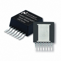
LMZ10504TZ-ADJ/NOPB National Semiconductor, LMZ10504TZ-ADJ/NOPB Datasheet - Page 8

LMZ10504TZ-ADJ/NOPB
Manufacturer Part Number
LMZ10504TZ-ADJ/NOPB
Description
IC BUCK SYNC ADJ 4A TO-PMOD-7
Manufacturer
National Semiconductor
Series
SIMPLE SWITCHER®r
Type
Point of Load (POL) Non-Isolated with UVLOr
Datasheet
1.LMZ10504TZ-ADJNOPB.pdf
(22 pages)
Specifications of LMZ10504TZ-ADJ/NOPB
Output
0.8 ~ 5 V
Number Of Outputs
1
Power (watts)
20W
Mounting Type
Surface Mount
Voltage - Input
2.95 ~ 5.5 V
Package / Case
TO-PMOD-7, Power Module
1st Output
0.8 ~ 5 VDC @ 4A
Size / Dimension
0.40" L x 0.54" W x 0.18" H (10.16mm x 13.77mm x 4.57mm)
Power (watts) - Rated
20W
Operating Temperature
-40°C ~ 125°C
Efficiency
96%
Approvals
EN
Lead Free Status / RoHS Status
Lead free / RoHS Compliant
3rd Output
-
2nd Output
-
Other names
LMZ10504TZ-ADJTR
Available stocks
Company
Part Number
Manufacturer
Quantity
Price
Company:
Part Number:
LMZ10504TZ-ADJ/NOPB
Manufacturer:
NS
Quantity:
1 000
www.national.com
Block Diagram
General Description
The LMZ10504 SIMPLE SWITCHER® power module is a
complete, easy-to-use DC-DC solution capable of driving up
to a 4A load with exceptional power conversion efficiency,
output voltage accuracy, line and load regulation. The
LMZ10504 is available in an innovative package that en-
hances thermal performance and allows for hand or machine
soldering.
The LMZ10504 can accept an input voltage rail between
2.95V and 5.5V and deliver an adjustable and highly accurate
output voltage as low as 0.8V. One megahertz fixed frequen-
cy PWM switching provides a predictable EMI characteristic.
Two external compensation components can be adjusted to
set the fastest response time, while allowing the option to use
ceramic and/or electrolytic output capacitors. Externally pro-
grammable soft-start capacitor facilitates controlled startup.
The LMZ10504 is a reliable and robust solution with the fol-
lowing features: lossless cycle-by-cycle peak current limit to
protect for over current or short-circuit fault, thermal shut-
down, input under-voltage lock-out, and pre-biased startup.
Design Guideline And Operating
Description
Design Steps
LMZ10504 is fully supported by Webench® and offers the
following: component selection, performance, electrical, and
thermal simulations as well as the Build-It board, for a reduced
design time. On the other hand, all external components can
be calculated by following the design procedure below.
1. Determine the input voltage and output voltage. Also, make
note of the ripple voltage and voltage transient requirements.
2. Determine the necessary input and output capacitance.
3. Calculate the feedback resistor divider.
4. Select the optimized compensation component values.
5. Estimate the power dissipation and board thermal require-
ments.
8
6. Follow the PCB design guideline.
7. Learn about the LMZ10504 features such as enable, input
UVLO, soft-start, tracking, pre-biased startup, current limit,
and thermal shutdown.
Design Example
For this example the following application parameters exist.
•
•
•
•
•
Input Capacitor Selection
A 22 µF or 47 µF high quality dielectric (X5R, X7R) ceramic
capacitor rated at twice the maximum input voltage is typically
sufficient. The input capacitor must be placed as close as
possible to the VIN pin and GND exposed pad to substantially
eliminate the parasitic effects of any stray inductance or re-
sistance on the PC board and supply lines.
Neglecting capacitor equivalent series resistance (ESR), the
resultant input capacitor AC ripple voltage is a triangular
waveform. The minimum input capacitance for a given peak-
to-peak value (ΔV
where the PWM duty cycle, D, is given by:
If ΔV
V
V
I
ΔV
ΔV
OUT
IN
OUT
IN
OUT
o_tran
= 5V
is 1% of V
= 4A
= 2.5V
= 20 mV
= ±20 mV
IN
IN
pk-pk
, this equals to 50 mV and f
) of V
pk-pk
IN
is specified as follows:
30088236
SW
= 1 MHz


