AD5247EVAL Analog Devices Inc, AD5247EVAL Datasheet - Page 16
AD5247EVAL
Manufacturer Part Number
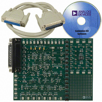
AD5247EVAL
Description
BOARD EVAL FOR AD5247
Manufacturer
Analog Devices Inc
Datasheet
1.AD5247BKSZ50-RL7.pdf
(20 pages)
Specifications of AD5247EVAL
Main Purpose
Digital Potentiometer
Utilized Ic / Part
AD5247
Lead Free Status / RoHS Status
Contains lead / RoHS non-compliant
Secondary Attributes
-
Embedded
-
Primary Attributes
-


AD5247
LEVEL SHIFTING FOR BIDIRECTIONAL INTERFACE
While most legacy systems can be operated at one voltage, a
new component can be optimized at another voltage. When
two systems operate the same signal at two different voltages,
proper level shifting is needed. For instance, users can employ
a 3.3 V E
level shifting scheme is needed to enable a bidirectional commu-
nication so that the setting of the digital potentiometer can be
stored in and retrieved from the E
of the level-shifting implementations. M1 and M2 can be any
N-channel signal FETs, or if V
can be low threshold FETs such as the FDV301N.
ESD PROTECTION
All digital inputs are protected with a series input resistor and
parallel Zener ESD structures as shown in Figure 37. This applies
to digital input pins (SDA and SCL).
TERMINAL VOLTAGE OPERATING RANGE
The AD5247 V
conditions for proper 3-terminal digital potentiometer operation.
Supply signals present on Terminal A and Terminal W that exceed
V
(see Figure 38).
DD
V
SDA1
SCL1
DD1
or GND are clamped by the internal forward biased diodes
Figure 36. Level-Shifting for Operation at Different Potentials
Figure 38. Maximum Terminal Voltages Set by V
= 3.3V
2
PROM to interface with a 5 V digital potentiometer. A
E
2
3.3V
PROM
R
DD
Figure 37. ESD Protection of Digital Pins
P
and GND power supply defines the boundary
SDA/
SCL
R
P
S
G
M1
340Ω
D
DD
GND
S
falls below 2.5 V, M1 and M2
G
M2
2
PROM. Figure 36 shows one
LOGIC
D
R
P
AD5247
R
P
5V
V
DD
DD2 =
V
A
W
GND
DD
and GND
5V
SDA2
SCL2
Rev. E | Page 16 of 20
MAXIMUM OPERATING CURRENT
At low code values, the user should be aware that, due to low
resistance values, the current through the RDAC might exceed
the 5 mA limit. In Figure 39, a 5 V supply is placed on the wiper,
and the current through Terminal W and Terminal B is plotted
with respect to code. A line is also drawn denoting the 5 mA
current limit. Note that at low code values (particularly for the
5 kΩ and 10 kΩ options), the current level increases signifi-
cantly. Care should be taken to limit the current flow between
W and B in this state to a maximum continuous current of
5 mA and a maximum pulse current of no more than 20 mA.
Otherwise, degradation or possible destruction of the internal
switch contacts can occur.
POWER-UP SEQUENCE
Because the ESD protection diodes limit the voltage compliance
at Terminal A and Terminal W (see Figure 38), it is important
to power V
and Terminal W; otherwise, the diode is forward-biased such
that V
user’s circuit. The ideal power-up sequence is in the following
order: GND, V
of powering V
as long as they are powered after V
DD
0.01
100
0.1
10
is powered unintentionally and can affect the rest of the
1
0
DD
/GND before applying any voltage to Terminal A
A
DD
Figure 39. Maximum Operating Current
16
and V
, digital inputs, V
32
W
and the digital inputs is not important
5mA CURRENT LIMIT
48
CODE (Decimal)
64
A
DD
, and V
/GND.
R
AB
80
= 10kΩ
R
AB
W
. The relative order
= 100kΩ
R
96
R
AB
AB
= 5kΩ
= 50kΩ
112
128
Related parts for AD5247EVAL
Image
Part Number
Description
Manufacturer
Datasheet
Request
R


Part Number:
Description:
±1.7g Dual-Axis IMEMS Accelerometer Evaluation Board
Manufacturer:
Analog Devices Inc
Datasheet:

Part Number:
Description:
Inertial Sensor Evaluation System
Manufacturer:
Analog Devices Inc
Datasheet:
Part Number:
Description:
Manufacturer:
Analog Devices Inc
Datasheet:
Part Number:
Description:
Manufacturer:
Analog Devices Inc
Datasheet:
Part Number:
Description:
Manufacturer:
Analog Devices Inc
Datasheet:
Part Number:
Description:
Manufacturer:
Analog Devices Inc
Datasheet:
Part Number:
Description:
Manufacturer:
Analog Devices Inc
Datasheet:
Part Number:
Description:
Manufacturer:
Analog Devices Inc
Datasheet:
Part Number:
Description:
Manufacturer:
Analog Devices Inc
Datasheet:
Part Number:
Description:
Manufacturer:
Analog Devices Inc
Datasheet:
Part Number:
Description:
Manufacturer:
Analog Devices Inc
Datasheet:
Part Number:
Description:
Manufacturer:
Analog Devices Inc
Datasheet: