AD5247EVAL Analog Devices Inc, AD5247EVAL Datasheet - Page 17
AD5247EVAL
Manufacturer Part Number
AD5247EVAL
Description
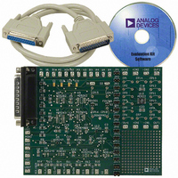
BOARD EVAL FOR AD5247
Manufacturer
Analog Devices Inc
Datasheet
1.AD5247BKSZ50-RL7.pdf
(20 pages)
Specifications of AD5247EVAL
Main Purpose
Digital Potentiometer
Utilized Ic / Part
AD5247
Lead Free Status / RoHS Status
Contains lead / RoHS non-compliant
Secondary Attributes
-
Embedded
-
Primary Attributes
-


LAYOUT AND POWER SUPPLY BYPASSING
It is good practice to employ a compact, minimum lead-length
layout design. The leads to the inputs should be as direct as pos-
sible with minimum conductor length. Ground paths should
have low resistance and low inductance.
Similarly, it is good practice to bypass the power supplies with
quality capacitors for optimum stability. Supply leads to the device
should be bypassed with 0.01 µF to 0.1 µF disc or chip ceramic
capacitors. Low ESR 1 µF to 10 µF tantalum or electrolytic capaci-
tors should also be applied at the supplies to minimize any transient
disturbance and low frequency ripple (see Figure 40). Note that the
digital ground should also be joined remotely to the analog ground
at one point to minimize the ground bounce.
CONSTANT BIAS TO RETAIN RESISTANCE SETTING
For users who desire nonvolatility but cannot justify the additional
cost for the EEMEM, the AD5247 can be considered a low cost
alternative because it maintains a constant bias to retain the
wiper setting. The AD5247 is specifically designed with low
power in mind, which allows low power consumption even in
battery-operated systems.
Figure 41 demonstrates the power consumption from a 3.4 V
450 mA/hr Li-Ion cell phone battery, which is connected to the
AD5247. The measurement over time shows that the device
draws approximately 1.3 µA and consumes negligible power.
Over a course of 30 days, the battery was depleted by less than
2%, the majority of which was due to the intrinsic leakage
current of the battery itself.
V
10µF
DD
C3
Figure 40. Power Supply Bypassing
+
0.1µF
C1
V
DD
AD5247
GND
Rev. E | Page 17 of 20
This demonstrates that constantly biasing the potentiometer
is a practical approach. Most portable devices do not require
the removal of batteries for charging. Although the resistance
setting of the AD5247 is lost when the battery needs replace-
ment, such events occur rather infrequently. As a result, this
inconvenience is justified by the lower cost and smaller size
offered by the AD5247. If total power is lost, the user should
be provided with a means to adjust the setting accordingly.
EVALUATION BOARD
An evaluation board, along with all necessary software, is avail-
able to program the AD5247 from any PC running Windows® 98,
Windows 2000, or Windows XP. The graphical user interface,
shown in Figure 42, is straightforward and easy to use. More
information is available in the data sheet that comes with the
evaluation board.
100%
104%
102%
110%
108%
106%
96%
94%
92%
90%
98%
0
Figure 42. AD5247 Evaluation Board Software
Figure 41. Battery Operating Life Depletion
5
10
DAYS
15
20
T
A
= 25°C
25
AD5247
30
Related parts for AD5247EVAL
Image
Part Number
Description
Manufacturer
Datasheet
Request
R


Part Number:
Description:
±1.7g Dual-Axis IMEMS Accelerometer Evaluation Board
Manufacturer:
Analog Devices Inc
Datasheet:

Part Number:
Description:
Inertial Sensor Evaluation System
Manufacturer:
Analog Devices Inc
Datasheet:
Part Number:
Description:
Manufacturer:
Analog Devices Inc
Datasheet:
Part Number:
Description:
Manufacturer:
Analog Devices Inc
Datasheet:
Part Number:
Description:
Manufacturer:
Analog Devices Inc
Datasheet:
Part Number:
Description:
Manufacturer:
Analog Devices Inc
Datasheet:
Part Number:
Description:
Manufacturer:
Analog Devices Inc
Datasheet:
Part Number:
Description:
Manufacturer:
Analog Devices Inc
Datasheet:
Part Number:
Description:
Manufacturer:
Analog Devices Inc
Datasheet:
Part Number:
Description:
Manufacturer:
Analog Devices Inc
Datasheet:
Part Number:
Description:
Manufacturer:
Analog Devices Inc
Datasheet:
Part Number:
Description:
Manufacturer:
Analog Devices Inc
Datasheet: