AD5247EVAL Analog Devices Inc, AD5247EVAL Datasheet - Page 5
AD5247EVAL
Manufacturer Part Number
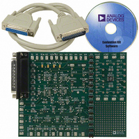
AD5247EVAL
Description
BOARD EVAL FOR AD5247
Manufacturer
Analog Devices Inc
Datasheet
1.AD5247BKSZ50-RL7.pdf
(20 pages)
Specifications of AD5247EVAL
Main Purpose
Digital Potentiometer
Utilized Ic / Part
AD5247
Lead Free Status / RoHS Status
Contains lead / RoHS non-compliant
Secondary Attributes
-
Embedded
-
Primary Attributes
-


6
7
8
TIMING CHARACTERISTICS—5 kΩ, 10 kΩ, 50 kΩ, AND 100 kΩ VERSIONS
V
Table 3.
Parameter
SCL Clock Frequency
Bus Free Time Between Stop and Start, t
Hold Time (Repeated Start), t
Low Period of SCL Clock, t
High Period of SCL Clock, t
Setup Time for Repeated Start Condition, t
Data Hold Time, t
Data Setup Time, t
Fall Time of Both SDA and SCL Signals, t
Rise Time of Both SDA and SCL Signals, t
Setup Time for Stop Condition, t
1
2
3
4
5
Guaranteed by design, not subject to production test.
P
All dynamic characteristics use V
Specifications apply to all parts.
Guaranteed by design, not subject to production test.
See timing diagrams (Figure 2, Figure 33, and Figure 34) for locations of measured values.
Typical specifications represent average readings at 25°C and V
After this period, the first clock pulse is generated.
DD
DISS
= 5 V ± 10% or 3 V ± 10%, V
is calculated from (I
SDA
SCL
1, 2, 3
P
HD;DAT
SU;DAT
t
1
DD
S
× V
DD
LOW
HIGH
). CMOS logic level inputs result in minimum power dissipation.
t
DD
2
HD;STA
= 5 V.
SU;STO
5
A
= V
t
3
t
F
DD
8
BUF
R
, −40°C < T
SU;STA
t
8
t
Figure 2. I
9
A
DD
t
6
< +125°C, unless otherwise noted.
= 5 V.
2
C Interface, Detailed Timing Diagram
t
9
t
4
Rev. E | Page 5 of 20
t
7
Symbol
f
t
t
t
t
t
t
t
t
t
t
SCL
1
2
3
4
5
6
7
8
9
10
S
t
5
t
2
Min
1.3
0.6
1.3
0.6
0.6
100
0.6
Typ
4
Max
400
50
0.9
300
300
t
10
P
AD5247
Unit
kHz
µs
µs
µs
µs
µs
µs
ns
ns
ns
µs
Related parts for AD5247EVAL
Image
Part Number
Description
Manufacturer
Datasheet
Request
R


Part Number:
Description:
±1.7g Dual-Axis IMEMS Accelerometer Evaluation Board
Manufacturer:
Analog Devices Inc
Datasheet:

Part Number:
Description:
Inertial Sensor Evaluation System
Manufacturer:
Analog Devices Inc
Datasheet:
Part Number:
Description:
Manufacturer:
Analog Devices Inc
Datasheet:
Part Number:
Description:
Manufacturer:
Analog Devices Inc
Datasheet:
Part Number:
Description:
Manufacturer:
Analog Devices Inc
Datasheet:
Part Number:
Description:
Manufacturer:
Analog Devices Inc
Datasheet:
Part Number:
Description:
Manufacturer:
Analog Devices Inc
Datasheet:
Part Number:
Description:
Manufacturer:
Analog Devices Inc
Datasheet:
Part Number:
Description:
Manufacturer:
Analog Devices Inc
Datasheet:
Part Number:
Description:
Manufacturer:
Analog Devices Inc
Datasheet:
Part Number:
Description:
Manufacturer:
Analog Devices Inc
Datasheet:
Part Number:
Description:
Manufacturer:
Analog Devices Inc
Datasheet: