CDB48500-USB Cirrus Logic Inc, CDB48500-USB Datasheet - Page 38
CDB48500-USB
Manufacturer Part Number
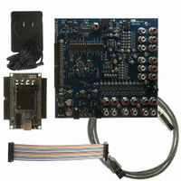
CDB48500-USB
Description
KIT USB EVALUATION FOR CDB48500
Manufacturer
Cirrus Logic Inc
Datasheet
1.CDB48500-USB.pdf
(52 pages)
Specifications of CDB48500-USB
Main Purpose
Audio, Audio Processing
Embedded
No
Utilized Ic / Part
CS485XX
Primary Attributes
32-Bit Audio Processor, I2C or SPI
Secondary Attributes
Graphic User Interface, 12-ch Analog Audio Input & Outputs, Optical Out- S/PDIF
Description/function
Audio A/D
Operating Supply Voltage
9 V to 12 V
Product
Audio Modules
Supply Current
1 A
For Use With/related Products
CS48520, CS48540, CS48560
Lead Free Status / RoHS Status
Contains lead / RoHS non-compliant
Lead Free Status / RoHS Status
Lead free / RoHS Compliant, Contains lead / RoHS non-compliant
Other names
598-1284


DS784DB1
The analog inputs and outputs of the CS42448 are being used in single-ended mode. This is evident
when looking at the input and output filter circuitry on page 6 of the schematics.
The transistor connected to MUTEC (Q11) provides the current drive necessary to drive all of the mute
transistors (see page 9 of schematic) into saturation.
Each output of the CS42448 has an output filter that consists of an AC-coupling cap (3.3 μF), a pull-down
resistor to prevent the output from floating when not connected to a load, a series resistor (470 Ω) to
provide a voltage drop when the muting transistor is enabled, and a mute transistor that will pull the output
low when the mute control signal is enabled. The series resistor is small enough that it does not affect the
signal in normal operation, assuming a load of at least 10 kΩ is connected to the analog output of the
board. The 12 RCA jacks for analog outputs are also shown on this page.
Each input of the CS42448 has its own input filter that consists of a voltage divider, an AC-coupling
capacitor (10 μF), and a anti-aliasing capacitor (2700 pF). The voltage divider is provided to make the
CDB48500 capable of accepting analog signals of up to 2 V
scale for an input amplitude of 1 V
A headphone Amp is provided on the AOUT7 and AOUT8 of the second CODEC. The output of the
headphone amp is connected to an 1/8” headphone output. The headphone maps to DAO2_D1 on the
DSP. Refer to section
output.
The CDB48500 has a 1/8” microphone input jack to allow direct connection to an encapsulated condenser
microphone (ECM). Because the output of the ECM is so small, a pre-amplifier is needed to boost the
signal to a line-level voltage.
These specifications for the amplifier are noted on the schematic page. These parameters should be
considered when choosing the microphone to be connected to the CDB48500. Too large of a signal on the
CS42448 analog input will result in distortion of the sampled signal.
It is important to note that although the amplifier circuit shown is non-inverting (the input to U12-B is the
same polarity as the output from U12-C), the output of an ECM is inherently inverted since it acts as an
open-collector device. Therefore the microphone signal driven to the CS42448 should be considered an
inverted signal for processing purposes.
There is one control connector on the board, J11. This 50-pin connector provides pins for the following
functions:
The DC input connector (J25) for the CDB48500 can accept 9 to 12 V
capable of supplying at least 1 amp of current.
The 3 voltage regulators on the CDB48500 generate the 1.8V, 3.3V, and 5V necessary for powering all of
the ICs on the board. Note that the 5 V and 3.3 V regulators run directly off the DC input supply connected
A.1.1.1.8 Codec 1 and Codec 2 Input Filters (See
A.1.1.1.9 Output Filters & Headphone Output (See
A.1.1.1.10 Mic and Pre-Amp (See
A.1.1.1.11 Control Connector and Power (See
• Serial control interface for configuring the DSP, codecs, and S/PDIF RX
• Reset lines for the DSP and other board devices
• Pins to provide power to the CDB USB MASTER USB control board
• An interface for delivering audio data to and from the USB board (feature not yet available)
Section 4.2.5, “Headphone Output” on page 4-8
RMS
©
Copyright 2008 Cirrus Logic , Inc.
. The 12 RCA jacks for analog inputs are also shown on this page.
Figure
A-10)
Figure
Figure
Figure
RMS
A-11)
. The CS42448 analog inputs register full-
A-8)
A-9)
DC
for more details on the headphone
, and the power supply should be
CDB48500--USB Evaluation Kit Guide
Introduction
A-4
Related parts for CDB48500-USB
Image
Part Number
Description
Manufacturer
Datasheet
Request
R

Part Number:
Description:
Development Kit
Manufacturer:
Cirrus Logic Inc
Datasheet:
Part Number:
Description:
Development Kit
Manufacturer:
Cirrus Logic Inc
Datasheet:


Part Number:
Description:
High-efficiency PFC + Fluorescent Lamp Driver Reference Design
Manufacturer:
Cirrus Logic Inc
Datasheet:
Part Number:
Description:
Development Kit
Manufacturer:
Cirrus Logic Inc
Datasheet:
Part Number:
Description:
Development Kit
Manufacturer:
Cirrus Logic Inc
Datasheet:

Part Number:
Description:
Development Kit
Manufacturer:
Cirrus Logic Inc
Datasheet:
Part Number:
Description:
Development Kit
Manufacturer:
Cirrus Logic Inc
Datasheet:
Part Number:
Description:
Development Kit
Manufacturer:
Cirrus Logic Inc
Datasheet:
Part Number:
Description:
Development Kit
Manufacturer:
Cirrus Logic Inc
Datasheet:

Part Number:
Description:
EVALUATION BOARD FOR CS8427
Manufacturer:
Cirrus Logic Inc
Datasheet:

Part Number:
Description:
BOARD EVAL FOR CS8416 RCVR
Manufacturer:
Cirrus Logic Inc
Datasheet:

Part Number:
Description:
EVALUATION BOARD FOR CS8420
Manufacturer:
Cirrus Logic Inc
Datasheet:

Part Number:
Description:
KIT DEVELOPMENT EP9315 ARM9
Manufacturer:
Cirrus Logic Inc
Datasheet:

Part Number:
Description:
KIT DEVELOPMENT EP9302 ARM9
Manufacturer:
Cirrus Logic Inc
Datasheet: