CP2201EK Silicon Laboratories Inc, CP2201EK Datasheet - Page 39
CP2201EK
Manufacturer Part Number
CP2201EK
Description
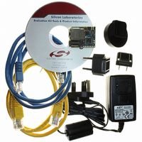
KIT EVAL FOR CP2201 ETH CTRLR
Manufacturer
Silicon Laboratories Inc
Type
Controllers & Processorsr
Specifications of CP2201EK
Main Purpose
Interface, Ethernet Sensor
Embedded
Yes, MCU, 8-Bit
Utilized Ic / Part
CP2200, CP2201
Primary Attributes
Temperature and Light Sensor
Secondary Attributes
Graphic User Interface
Interface Type
Ethernet
Product
Modules
Silicon Manufacturer
Silicon Labs
Silicon Core Number
CP2201
Silicon Family Name
CP220x
Kit Contents
CP2201 Evaluation Board, Power Adapter, CAT5e Ethernet Cable, CD-ROM, Quick-Start Guide
For Use With/related Products
CP2201
Lead Free Status / RoHS Status
Contains lead / RoHS non-compliant
Lead Free Status / RoHS Status
Lead free / RoHS Compliant, Contains lead / RoHS non-compliant
Other names
336-1316
Available stocks
Company
Part Number
Manufacturer
Quantity
Price
Company:

Part Number:
CP2201EK
Manufacturer:
SiliconL
Quantity:
8


9.2. Power-fail
When a power-down transition or power irregularity causes V
drive the /RST pin low and return the CP2200/1 to the reset state. When V
CP2200/1 will be released from the reset state as shown in Figure 14.
The power supply monitor circuit (V
every power-on reset. To prevent the device from being held in reset when V
may be deselected as a reset source (see RSTEN on page 42) and disabled (see VDMCN on page 39). It is
recommended to leave the V
9.3. Oscillator-Fail Reset
If the system clock derived from the oscillator fails for any reason after oscillator initialization is complete, the reset
circuitry will drive the /RST pin low and return the CP2200/1 to the reset state. The CP2200/1 will remain in the
reset state for approximately 1 ms then exit the reset state in the same manner as that for the power-on reset.
9.4. External Pin Reset
The external /RST pin provides a means for external circuitry to force the CP2200/1 into a reset state. Asserting the
/RST pin low will cause the CP2200/1 to enter the reset state. It is recommended to provide an external pull-up
and/or decoupling capacitor of the /RST pin to avoid erroneous noise-induced resets. The CP2200/1 will exit the
reset state approximately 4 µs after a logic high is detected on /RST.
Bit 7:
Bit6:
Bits 5–0: RESERVED. Read = varies; Write = don’t care.
VDMEN VDDSTAT Reserved Reserved Reserved Reserved Reserved Reserved 00000000
R/W
Bit7
VDMEN: V
This bit can be used to disable or enable the V
enabled and selected as a reset source following every power-on reset. If the V
disabled and then reenabled during device operation, it must be allowed to stabilize before it is
selected as a reset source. Selecting the V
generate a system reset. See Table 13 on page 42 for the minimum V
0: V
1: V
VDDSTAT: V
This bit indicates the current power supply status (V
0: V
1: V
DD
DD
DD
DD
R/W
Bit6
Monitor Disabled.
Monitor Enabled.
voltage is at or below the V
voltage is above the V
DD
Register 11. VDMCN: V
DD
Monitor Enable
Status
Bit5
DD
R
Monitor enabled and selected as a reset source at all times.
DD
Monitor) is enabled and selected as a reset source by hardware following
Bit4
R
DD
Monitor threshold.
DD
Monitor threshold.
Bit3
R
Rev. 1.0
DD
DD
Monitor Control Register
DD
Monitor as a reset source before it has stabilized will
DD
Monitor Circuit. Note: The V
Bit2
R
DD
to drop below V
Monitor output).
Bit1
R
DD
DD
drops below V
returns to a level above V
RST
, the power supply monitor will
DD
Bit0
R
Monitor turn-on time.
DD
CP2200/1
Monitor circuit is
Reset Value
RST
Address:
0x13
DD
, the V
Monitor is
DD
RST
Monitor
, the
39
Related parts for CP2201EK
Image
Part Number
Description
Manufacturer
Datasheet
Request
R

Part Number:
Description:
IC ETH CTRLR SNGL-CHIP 28QFN
Manufacturer:
Silicon Laboratories Inc
Datasheet:

Part Number:
Description:
Ethernet ICs Ethernet Controller
Manufacturer:
Silicon Laboratories Inc

Part Number:
Description:
SMD/C°/SINGLE-ENDED OUTPUT SILICON OSCILLATOR
Manufacturer:
Silicon Laboratories Inc
Part Number:
Description:
Manufacturer:
Silicon Laboratories Inc
Datasheet:
Part Number:
Description:
N/A N/A/SI4010 AES KEYFOB DEMO WITH LCD RX
Manufacturer:
Silicon Laboratories Inc
Datasheet:
Part Number:
Description:
N/A N/A/SI4010 SIMPLIFIED KEY FOB DEMO WITH LED RX
Manufacturer:
Silicon Laboratories Inc
Datasheet:
Part Number:
Description:
N/A/-40 TO 85 OC/EZLINK MODULE; F930/4432 HIGH BAND (REV E/B1)
Manufacturer:
Silicon Laboratories Inc
Part Number:
Description:
EZLink Module; F930/4432 Low Band (rev e/B1)
Manufacturer:
Silicon Laboratories Inc
Part Number:
Description:
I°/4460 10 DBM RADIO TEST CARD 434 MHZ
Manufacturer:
Silicon Laboratories Inc
Part Number:
Description:
I°/4461 14 DBM RADIO TEST CARD 868 MHZ
Manufacturer:
Silicon Laboratories Inc
Part Number:
Description:
I°/4463 20 DBM RFSWITCH RADIO TEST CARD 460 MHZ
Manufacturer:
Silicon Laboratories Inc
Part Number:
Description:
I°/4463 20 DBM RADIO TEST CARD 868 MHZ
Manufacturer:
Silicon Laboratories Inc
Part Number:
Description:
I°/4463 27 DBM RADIO TEST CARD 868 MHZ
Manufacturer:
Silicon Laboratories Inc
Part Number:
Description:
I°/4463 SKYWORKS 30 DBM RADIO TEST CARD 915 MHZ
Manufacturer:
Silicon Laboratories Inc