CRD3511-Q1 Cirrus Logic Inc, CRD3511-Q1 Datasheet - Page 13
CRD3511-Q1
Manufacturer Part Number
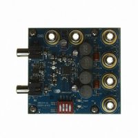
CRD3511-Q1
Description
BOARD REF CS3511 4LYR 1OZ CU
Manufacturer
Cirrus Logic Inc
Specifications of CRD3511-Q1
Amplifier Type
Class D
Output Type
2-Channel (Stereo)
Max Output Power X Channels @ Load
11.4W x 2 @ 6 Ohm
Voltage - Supply
8.5 V ~ 13.2 V
Operating Temperature
-10°C ~ 70°C
Board Type
Fully Populated
Utilized Ic / Part
CS3511
Product
Audio Modules
Lead Free Status / RoHS Status
Contains lead / RoHS non-compliant
Lead Free Status / RoHS Status
Lead free / RoHS Compliant, Contains lead / RoHS non-compliant
Other names
598-1577


DS845F1
4. APPLICATIONS
4.1
4.2
CS3511 Input Stage
The input stage of the CS3511 is configured as a differential receiver to maximize common-mode rejection
in typical audio circuits. To maximize this benefit, the INx+ and INx- pins should be driven with differential
signals from sources that have the same output impedance. Also, the signals should be routed parallel to
one another from their source to the analog inputs of the CS3511.
In some instances, there will be a necessity to drive the CS3511 with a single-ended input signal. In this
case, the unused input should be AC coupled to ground using the same value of C
driven channel. Either input, INx+ or INx-, can be used for the signal input. To minimize the effects of ground
noise in the system, C
to
Dynamic DC Offset Calibration
Abrupt changes in DC output offset level are a known cause of audible turn-on and turn-off pops. Typically,
when a system turns on (begins switching), the potential across the speaker changes abruptly from 0 V to
the steady-state DC offset voltage of the system. Similarly, when the system turns off, the potential changes
abruptly from the steady-state DC offset voltage to 0 V. These abrupt changes are heard as a pop.
The CS3511 employs a patented method for reducing this pop. Immediately before the outputs begin to
switch, a calibration circuit dynamically minimizes the amplifier’s internal offsets. With these offsets at a min-
imum, the outputs begin to switch and the CS3511 begins to slowly ramp the DC output offset potential to
the steady-state DC offset voltage. This ramp is slow enough to keep the speaker movement in the subsonic
range. During turn-off, this procedure is reversed. The static DC offset voltage is ramped down to a dynam-
ically minimized DC offset level before output switching is stopped.
Dynamic offset cancellation requires equal impedances on the positive and negative inputs. If a single-end-
ed audio source with a 600 Ω output impedance is connected to the IN1+ (through a DC blocking capacitor),
IN1- must be terminated to ground with a 600 Ω resistor (also through a DC blocking capacitor. (See
Figure
Figure
3).
3. The value of the resistor should match the output impedance of the audio source.
Audio Source
I
should be terminated at the ground connection through a resistor, R
Z
OUT
Figure 3. CS3511 Input Stage
R
I
C
C
= Z
I
I
OUT
CS3511
INx+
INx-
I
implemented for the
I
. Please refer
CS3511
13
Related parts for CRD3511-Q1
Image
Part Number
Description
Manufacturer
Datasheet
Request
R

Part Number:
Description:
Development Kit
Manufacturer:
Cirrus Logic Inc
Datasheet:
Part Number:
Description:
Development Kit
Manufacturer:
Cirrus Logic Inc
Datasheet:


Part Number:
Description:
High-efficiency PFC + Fluorescent Lamp Driver Reference Design
Manufacturer:
Cirrus Logic Inc
Datasheet:
Part Number:
Description:
Development Kit
Manufacturer:
Cirrus Logic Inc
Datasheet:
Part Number:
Description:
Development Kit
Manufacturer:
Cirrus Logic Inc
Datasheet:

Part Number:
Description:
Development Kit
Manufacturer:
Cirrus Logic Inc
Datasheet:
Part Number:
Description:
Development Kit
Manufacturer:
Cirrus Logic Inc
Datasheet:
Part Number:
Description:
Development Kit
Manufacturer:
Cirrus Logic Inc
Datasheet:
Part Number:
Description:
Development Kit
Manufacturer:
Cirrus Logic Inc
Datasheet:
Part Number:
Description:
Audio Modules & Development Tools EvalBd 30W Qd Hlf- Brdg Dig Amp Pwr Stg
Manufacturer:
Cirrus Logic Inc
Datasheet:

Part Number:
Description:
EVALUATION BOARD FOR CS8427
Manufacturer:
Cirrus Logic Inc
Datasheet:

Part Number:
Description:
BOARD EVAL FOR CS8416 RCVR
Manufacturer:
Cirrus Logic Inc
Datasheet:

Part Number:
Description:
EVALUATION BOARD FOR CS8420
Manufacturer:
Cirrus Logic Inc
Datasheet:

Part Number:
Description:
KIT DEVELOPMENT EP9315 ARM9
Manufacturer:
Cirrus Logic Inc
Datasheet: