CRD3511-Q1 Cirrus Logic Inc, CRD3511-Q1 Datasheet - Page 16
CRD3511-Q1
Manufacturer Part Number
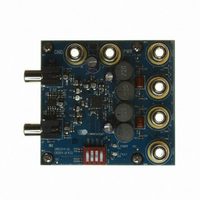
CRD3511-Q1
Description
BOARD REF CS3511 4LYR 1OZ CU
Manufacturer
Cirrus Logic Inc
Specifications of CRD3511-Q1
Amplifier Type
Class D
Output Type
2-Channel (Stereo)
Max Output Power X Channels @ Load
11.4W x 2 @ 6 Ohm
Voltage - Supply
8.5 V ~ 13.2 V
Operating Temperature
-10°C ~ 70°C
Board Type
Fully Populated
Utilized Ic / Part
CS3511
Product
Audio Modules
Lead Free Status / RoHS Status
Contains lead / RoHS non-compliant
Lead Free Status / RoHS Status
Lead free / RoHS Compliant, Contains lead / RoHS non-compliant
Other names
598-1577


16
4.10
4.11
continuous heavy load conditions. There should be vias for connecting the exposed pad to the copper area
on the printed circuit board. The pad must be electrically connected to PGND. See
formation on the thermal pad and
Performance Measurements of the CS3511
The CS3511 operates by generating a high-frequency switching signal based on the audio input. This signal
is sent through a low-pass filter (external to the CS3511 amplifier) that recovers an amplified version of the
audio input. The frequency of the switching pattern is spread spectrum and typically varies between 100 kHz
and 1.0 MHz, which is well above the 10 Hz – 20 kHz audio band. The pattern itself does not alter or distort
the audio input signal, but it does introduce some inaudible components outside of the audio band.
The measurements of certain performance parameters, particularly noise-related specifications such as
THD+N, are significantly affected by the design of the low-pass filter used on the output as well as the band-
width setting of the measurement instrument used. Unless the filter has a very sharp roll-off just beyond the
audio band or the bandwidth of the measurement instrument is limited, some of the inaudible components
introduced by the CS3511 amplifier’s switching pattern will degrade the measurement result.
One feature of the CS3511 is that it does not require large multi-pole filters to achieve excellent performance
in listening tests, usually a more critical factor than performance measurements. The CRD3511 Evaluation
Board uses the filter described in
formance in listening tests. Measurements in this data sheet were taken using this same circuit with a limited
bandwidth setting in the measurement instrument.
Full-Bridge Output Filter
Figure 4
(snubber circuit) is comprised of a resistor (5.6 Ω) and capacitor (680 pF) and should be placed as close
as possible to the corresponding PWM output pins to greatly reduce radiated EMI. The inductors, L1 and
L2, and capacitor, C1, comprise the low-pass filter. Along with the nominal load impedance of the speaker,
these values set the cutoff frequency of the filter.
speaker (load) impedance for a corner frequency (-3 dB point) of approximately 35 kHz.
shows the output filter for a full-bridge configuration. The transient-voltage suppression circuit
OUTx+
OUTx-
Load
8 Ω
6 Ω
680 pF
680 pF
5.6 Ω
5.6 Ω
Section
Section 9.1
Table 2. Low-Pass Filter Components
4.11, which has a simple two-pole output filter and excellent per-
Figure 4. Output Filter
for more information on thermal dissipation for the CS3511.
Table 2
L1, L2
22 µH
15 µH
shows the component values based on nominal
L1
L2
C1
0.47 µF
0.47 µF
C1
Section 5.2
CS3511
for more in-
DS845F1
Related parts for CRD3511-Q1
Image
Part Number
Description
Manufacturer
Datasheet
Request
R

Part Number:
Description:
Development Kit
Manufacturer:
Cirrus Logic Inc
Datasheet:
Part Number:
Description:
Development Kit
Manufacturer:
Cirrus Logic Inc
Datasheet:


Part Number:
Description:
High-efficiency PFC + Fluorescent Lamp Driver Reference Design
Manufacturer:
Cirrus Logic Inc
Datasheet:
Part Number:
Description:
Development Kit
Manufacturer:
Cirrus Logic Inc
Datasheet:
Part Number:
Description:
Development Kit
Manufacturer:
Cirrus Logic Inc
Datasheet:

Part Number:
Description:
Development Kit
Manufacturer:
Cirrus Logic Inc
Datasheet:
Part Number:
Description:
Development Kit
Manufacturer:
Cirrus Logic Inc
Datasheet:
Part Number:
Description:
Development Kit
Manufacturer:
Cirrus Logic Inc
Datasheet:
Part Number:
Description:
Development Kit
Manufacturer:
Cirrus Logic Inc
Datasheet:
Part Number:
Description:
Audio Modules & Development Tools EvalBd 30W Qd Hlf- Brdg Dig Amp Pwr Stg
Manufacturer:
Cirrus Logic Inc
Datasheet:

Part Number:
Description:
EVALUATION BOARD FOR CS8427
Manufacturer:
Cirrus Logic Inc
Datasheet:

Part Number:
Description:
BOARD EVAL FOR CS8416 RCVR
Manufacturer:
Cirrus Logic Inc
Datasheet:

Part Number:
Description:
EVALUATION BOARD FOR CS8420
Manufacturer:
Cirrus Logic Inc
Datasheet:

Part Number:
Description:
KIT DEVELOPMENT EP9315 ARM9
Manufacturer:
Cirrus Logic Inc
Datasheet: