CRD3511-Q1 Cirrus Logic Inc, CRD3511-Q1 Datasheet - Page 2
CRD3511-Q1
Manufacturer Part Number
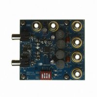
CRD3511-Q1
Description
BOARD REF CS3511 4LYR 1OZ CU
Manufacturer
Cirrus Logic Inc
Specifications of CRD3511-Q1
Amplifier Type
Class D
Output Type
2-Channel (Stereo)
Max Output Power X Channels @ Load
11.4W x 2 @ 6 Ohm
Voltage - Supply
8.5 V ~ 13.2 V
Operating Temperature
-10°C ~ 70°C
Board Type
Fully Populated
Utilized Ic / Part
CS3511
Product
Audio Modules
Lead Free Status / RoHS Status
Contains lead / RoHS non-compliant
Lead Free Status / RoHS Status
Lead free / RoHS Compliant, Contains lead / RoHS non-compliant
Other names
598-1577


2
TABLE OF CONTENTS
1. PIN DESCRIPTIONS .............................................................................................................................. 4
2. CHARACTERISTICS AND SPECIFICATIONS ...................................................................................... 6
3. TYPICAL CONNECTION DIAGRAMS ................................................................................................. 11
4. APPLICATIONS ................................................................................................................................... 13
5. POWER SUPPLY, GROUNDING, AND PCB LAYOUT ....................................................................... 17
6. TYPICAL AUDIO PERFORMANCE PLOTS ........................................................................................ 18
7. PARAMETER DEFINITIONS ................................................................................................................ 22
8. PACKAGE DIMENSIONS .................................................................................................................... 23
9. THERMAL CHARACTERISTICS ......................................................................................................... 24
10. ORDERING INFORMATION .............................................................................................................. 25
11. REVISION HISTORY .......................................................................................................................... 26
RECOMMENDED OPERATING CONDITIONS .................................................................................... 6
ABSOLUTE MAXIMUM RATINGS ........................................................................................................ 6
AC ELECTRICAL CHARACTERISTICS ................................................................................................ 7
DC ELECTRICAL CHARACTERISTICS ................................................................................................ 9
DIGITAL INTERFACE SPECIFICATIONS ............................................................................................. 9
DIGITAL I/O PIN CHARACTERISTICS ............................................................................................... 10
4.1 CS3511 Input Stage ....................................................................................................................... 13
4.2 Dynamic DC Offset Calibration ...................................................................................................... 13
4.3 CS3511 Amplifier Gain .................................................................................................................. 14
4.4 MUTE Pin ....................................................................................................................................... 14
4.5 SLEEP Pin ..................................................................................................................................... 14
4.6 Power Up and Power Down Sequence .......................................................................................... 14
4.7 Protection Circuits .......................................................................................................................... 15
4.8 Integrated 5 V Regulator ................................................................................................................ 15
4.9 Power Dissipation De-Rating ......................................................................................................... 15
4.10 Performance Measurements of the CS3511 ................................................................................ 16
4.11 Full-Bridge Output Filter ............................................................................................................... 16
5.1 Power Supply and Grounding ........................................................................................................ 17
5.2 QFN Thermal Pad .......................................................................................................................... 17
5.3 Layout Considerations ................................................................................................................... 17
9.1 Thermal Flag .................................................................................................................................. 24
4.6.1 Recommended Power-Up Sequence .................................................................................... 14
4.6.2 Recommended Power-Down Sequence ............................................................................... 15
4.7.1 Under-Voltage Protection ...................................................................................................... 15
4.7.2 Over-Temperature Protection ................................................................................................ 15
4.7.3 Over-Current Protection ........................................................................................................ 15
5.1.1 Maximum Supply Voltage ...................................................................................................... 17
CS3511
DS845F1
Related parts for CRD3511-Q1
Image
Part Number
Description
Manufacturer
Datasheet
Request
R

Part Number:
Description:
Development Kit
Manufacturer:
Cirrus Logic Inc
Datasheet:
Part Number:
Description:
Development Kit
Manufacturer:
Cirrus Logic Inc
Datasheet:


Part Number:
Description:
High-efficiency PFC + Fluorescent Lamp Driver Reference Design
Manufacturer:
Cirrus Logic Inc
Datasheet:
Part Number:
Description:
Development Kit
Manufacturer:
Cirrus Logic Inc
Datasheet:
Part Number:
Description:
Development Kit
Manufacturer:
Cirrus Logic Inc
Datasheet:

Part Number:
Description:
Development Kit
Manufacturer:
Cirrus Logic Inc
Datasheet:
Part Number:
Description:
Development Kit
Manufacturer:
Cirrus Logic Inc
Datasheet:
Part Number:
Description:
Development Kit
Manufacturer:
Cirrus Logic Inc
Datasheet:
Part Number:
Description:
Development Kit
Manufacturer:
Cirrus Logic Inc
Datasheet:
Part Number:
Description:
Audio Modules & Development Tools EvalBd 30W Qd Hlf- Brdg Dig Amp Pwr Stg
Manufacturer:
Cirrus Logic Inc
Datasheet:

Part Number:
Description:
EVALUATION BOARD FOR CS8427
Manufacturer:
Cirrus Logic Inc
Datasheet:

Part Number:
Description:
BOARD EVAL FOR CS8416 RCVR
Manufacturer:
Cirrus Logic Inc
Datasheet:

Part Number:
Description:
EVALUATION BOARD FOR CS8420
Manufacturer:
Cirrus Logic Inc
Datasheet:

Part Number:
Description:
KIT DEVELOPMENT EP9315 ARM9
Manufacturer:
Cirrus Logic Inc
Datasheet: