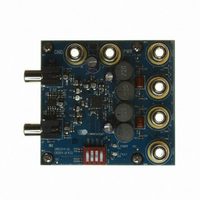
CRD3511-Q1 Cirrus Logic Inc, CRD3511-Q1 Datasheet - Page 14

CRD3511-Q1
Manufacturer Part Number
CRD3511-Q1
Description
BOARD REF CS3511 4LYR 1OZ CU
Manufacturer
Cirrus Logic Inc
Specifications of CRD3511-Q1
Amplifier Type
Class D
Output Type
2-Channel (Stereo)
Max Output Power X Channels @ Load
11.4W x 2 @ 6 Ohm
Voltage - Supply
8.5 V ~ 13.2 V
Operating Temperature
-10°C ~ 70°C
Board Type
Fully Populated
Utilized Ic / Part
CS3511
Product
Audio Modules
Lead Free Status / RoHS Status
Contains lead / RoHS non-compliant
Lead Free Status / RoHS Status
Lead free / RoHS Compliant, Contains lead / RoHS non-compliant
Other names
598-1577
14
4.3
4.4
4.5
4.6
4.6.1
CS3511 Amplifier Gain
The closed-loop gain of the CS3511 is externally configured via two input pins, GAIN0 and GAIN1. The
Electrical Characteristics
GAIN0 and GAIN1. The GAIN0 and GAIN1 input pins have weak internal pull-down resistors; so they should
be driven high when set to a logic high. Internally, different input resistor values are used to implement the
four gain settings. Thus, the input impedance will change based on the gain setting. The gain tracking is
very tightly matched within each device, but the absolute input impedance will vary due to process varia-
tions. This variation must be considered when choosing the proper value of C
characteristic is dedicated by the choice of C
The -3 dB frequency is:
On the CRD3511, a value of 1.0 µF is used for C
even for the highest gain setting. In many cases, a lower value of C
or because the speakers used do not have the ability to reproduce low-frequency signals.
MUTE Pin
The MUTE pin must be driven to a logic low or logic high state for proper operation. To enable the amplifier,
connect the MUTE pin to a logic low. To enable the mute function, connect the MUTE pin to a logic high
signal.
When in mute, the internal processor bias voltages remain active in the CS3511. This state maintains the
bias on the input coupling capacitor to prevent audible transients which would be caused by the charging
and discharging of this capacitor. It is recommended that the MUTE pin be held high during power-up or
power-down to eliminate audible transients.
If power-up and/or power-down pops are present with a CS3511 amplifier, the cause may be other circuitry
external to the CS3511, such as an audio processor or preamp. If the CS3511 is in the active state (MUTE
pin is low), these audible pops will be amplified and output to the speakers. To eliminate this problem, acti-
vate the MUTE pin before the power supply collapses during a power-down sequence.
SLEEP Pin
When pulled high, the SLEEP pin puts the device into a low quiescent current mode. To disable sleep mode,
the SLEEP pin should be grounded. While the device is in low power mode the STATUS pin will be in a logic
high state to indicate that the device is not ready to produce audio.
Power Up and Power Down Sequence
To minimize power-on and power-off transients, the device should be held in the MUTE state while powering
up or powering down the CS3511. The SLEEP pin can be held in either the logic high state or logic low state
during power-up or power-down.
Recommended Power-Up Sequence
1. Apply power to the system.
2. Hold the MUTE pin in the logic high state until the power supply is stable. In this state, all associated
3. Set the MUTE pin to a logic low state to begin normal operation. If the SLEEP pin is held high during
f
outputs are held in a high-impedance state.
power-on (optional), it should be set low before the MUTE pin is set low.
c - 3 dB
=
2 π C
1
I
R
table show the four different gain values available based on the pin voltages at
I
I
and R
I
; this value provides a nearly flat response down to 20 Hz,
I
.
I
can be used due to a lower gain setting
I
. The low-frequency roll-off
CS3511
DS845F1
AC


