ADP2114-2PH-EVALZ Analog Devices Inc, ADP2114-2PH-EVALZ Datasheet - Page 17
ADP2114-2PH-EVALZ
Manufacturer Part Number
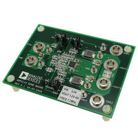
ADP2114-2PH-EVALZ
Description
BOARD EVALUATION 1.2V 4A 1.2MHZ
Manufacturer
Analog Devices Inc
Type
Evaluation Boardr
Specifications of ADP2114-2PH-EVALZ
Design Resources
Powering AD9268 with ADP2114 for Increased Efficiency (CN0137)
Main Purpose
DC/DC, Step Down
Outputs And Type
1, Non-Isolated
Voltage - Output
0.6 ~ 3.3 V
Current - Output
4A
Voltage - Input
2.75 ~ 5.5 V
Regulator Topology
Buck
Frequency - Switching
300kHz, 600kHz, 1.2MHz
Board Type
Fully Populated
Utilized Ic / Part
ADP2114
Svhc
No SVHC (18-Jun-2010)
Kit Features
DC-to-DC Switching Regulator, Standalone Capability, Configurable SYNC Input Or CLOCKOUT Output
Mcu Supported Families
ADP2114
Silicon Manufacturer
Analog Devices
Kit Contents
Board
Features
Standalone Capability, Two Independent Enable Inputs, Two Power Good Outputs
Core Architecture
Power
Rohs Compliant
Yes
Kit Application Type
Power Management
Application Sub Type
Step Down DC/DC Regulator
Lead Free Status / RoHS Status
Lead free / RoHS Compliant
Power - Output
-
Lead Free Status / RoHS Status
Lead free / RoHS Compliant, Lead free / RoHS Compliant
Available stocks
Company
Part Number
Manufacturer
Quantity
Price
Company:

Part Number:
ADP2114-2PH-EVALZ
Manufacturer:
Analog Devices Inc
Quantity:
135


1
2
4
3
4
2
3
4
2
3
CH1 5.0V
CH3 5.0V
CH3 5.0V
CH3 5.0V
Channel 2 V
Channel 2 V
EN2
V
SS2
SW
OUT2
Figure 55. Current Limit Entry (Zoomed In),
Figure 53. Start with Precharged Output
CH2 1.0V
CH4 500mV
CH2 1.0V
CH4 2.0A
CH2 1.0V
CH4 2.0A
OUT
OUT
Figure 54. Current Limit Entry,
= 1.8 V, 2 A Configuration, f
= 1.8 V, 2 A Configuration, f
M200µs
M1.0ms
M10.0µs
INDUCTOR CURRENT
V
SW
INDUCTOR CURRENT
V
SW
OUT2
OUT2
A CH2
A CH2
SW
SW
A CH1
= 600 kHz
= 600 kHz
1.12V
1.12V
2.4V
Rev. 0 | Page 17 of 40
Figure 58. External Synchronization, f
4
2
3
4
2
3
1
4
3
Figure 56. Hiccup Mode, f
CH3 5.0V
CH3 5.0V
CH1 5.0V
CH3 5.0V
EXTERNAL SYNC
CHANNEL 1 SW
CHANNEL 2 SW
Channel 2 V
CH2 1.0V
CH4 2.0A
CH2 1.0V
CH4 2.0A
CH4 5.0V
Figure 57. Exit Hiccup Mode,
INDUCTOR CURRENT
V
SW
OUT
OUT
SW
= 1.8 V, f
M2.0ms
M2.0ms
M1.0µs
= 600 kHz, 6.8 ms Hiccup Cycle
SYNC
SW
INDUCTOR CURRENT
V
SW
OUT
= 600 kHz
= 1.5 MHz, f
A CH4
A CH2
A CH1
SW
ADP2114
= 750 kHz
1.72V
1.12V
3.0V
Related parts for ADP2114-2PH-EVALZ
Image
Part Number
Description
Manufacturer
Datasheet
Request
R

Part Number:
Description:
BOARD EVALUATION 3.3V/1.8V
Manufacturer:
Analog Devices Inc
Datasheet:

Part Number:
Description:
Configurable, Dual 2 A/Single 4 A, Synchronous Step-Down DC-to-DC Regulator
Manufacturer:
Analog Devices
Datasheet:

Part Number:
Description:
Blank ADISimPower Eval ADP2114
Manufacturer:
Analog Devices Inc
Datasheet:

Part Number:
Description:
±1.7g Dual-Axis IMEMS Accelerometer Evaluation Board
Manufacturer:
Analog Devices Inc
Datasheet:
Part Number:
Description:
Inertial Sensor Evaluation System
Manufacturer:
Analog Devices Inc
Datasheet:
Part Number:
Description:
Manufacturer:
Analog Devices Inc
Datasheet:
Part Number:
Description:
Manufacturer:
Analog Devices Inc
Datasheet:
Part Number:
Description:
Manufacturer:
Analog Devices Inc
Datasheet:
Part Number:
Description:
Manufacturer:
Analog Devices Inc
Datasheet:
Part Number:
Description:
Manufacturer:
Analog Devices Inc
Datasheet:
Part Number:
Description:
Manufacturer:
Analog Devices Inc
Datasheet:
Part Number:
Description:
Manufacturer:
Analog Devices Inc
Datasheet:
Part Number:
Description:
Manufacturer:
Analog Devices Inc
Datasheet: