ADP2114-2PH-EVALZ Analog Devices Inc, ADP2114-2PH-EVALZ Datasheet - Page 21
ADP2114-2PH-EVALZ
Manufacturer Part Number
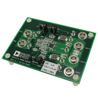
ADP2114-2PH-EVALZ
Description
BOARD EVALUATION 1.2V 4A 1.2MHZ
Manufacturer
Analog Devices Inc
Type
Evaluation Boardr
Specifications of ADP2114-2PH-EVALZ
Design Resources
Powering AD9268 with ADP2114 for Increased Efficiency (CN0137)
Main Purpose
DC/DC, Step Down
Outputs And Type
1, Non-Isolated
Voltage - Output
0.6 ~ 3.3 V
Current - Output
4A
Voltage - Input
2.75 ~ 5.5 V
Regulator Topology
Buck
Frequency - Switching
300kHz, 600kHz, 1.2MHz
Board Type
Fully Populated
Utilized Ic / Part
ADP2114
Svhc
No SVHC (18-Jun-2010)
Kit Features
DC-to-DC Switching Regulator, Standalone Capability, Configurable SYNC Input Or CLOCKOUT Output
Mcu Supported Families
ADP2114
Silicon Manufacturer
Analog Devices
Kit Contents
Board
Features
Standalone Capability, Two Independent Enable Inputs, Two Power Good Outputs
Core Architecture
Power
Rohs Compliant
Yes
Kit Application Type
Power Management
Application Sub Type
Step Down DC/DC Regulator
Lead Free Status / RoHS Status
Lead free / RoHS Compliant
Power - Output
-
Lead Free Status / RoHS Status
Lead free / RoHS Compliant, Lead free / RoHS Compliant
Available stocks
Company
Part Number
Manufacturer
Quantity
Price
Company:

Part Number:
ADP2114-2PH-EVALZ
Manufacturer:
Analog Devices Inc
Quantity:
135


THEORY OF OPERATION
The ADP2114 is a high efficiency, dual, fixed switching frequency,
synchronous step-down, dc-to-dc converter with flex mode
architecture, which is the Analog Devices, Inc., proprietary
version of its peak current mode control architecture. The
device operates over an input voltage range of 2.75 V to 5.5 V.
Each output channel provides an adjustable output down to 0.6 V
and delivers up to 2 A of load current. When both the output
channels are tied together, they operate 180° out of phase to
deliver up to 4 A of load current. The integrated high-side,
P-channel power MOSFET and the low-side, N-channel power
MOSFET yield high efficiency at medium to heavy loads. Pulse
skip mode is available for improved efficiency at light loads. With
its high switching frequency (up to 2 MHz) and its integrated
power switches, the ADP2114 has been optimized to deliver
high performance in a small size for power management solutions.
The ADP2114 also includes undervoltage lockout (UVLO) with
hysteresis, soft start, and power good, as well as protection
features such as output short-circuit protection and thermal
shutdown. The output voltages, current limits, switching
frequency, pulse skip operation, and soft start time are
externally programmable with tiny resistors and capacitors.
CONTROL ARCHITECTURE
The ADP2114 consists of two step-down, dc-to-dc converters
that deliver regulated output voltages, V
Figure 1), by modulating the duty cycle at which the internal
high-side, P-channel power MOSFET and the low-side, N-channel
power MOSFET are switched on and off. In steady-state operation,
the output voltage, V
and attenuated in proportion to the selected output voltage on
the V1SET (V2SET) pin. An error amplifier integrates the error
between the feedback voltage and the reference voltage (V
0.6 V) to generate an error voltage at the COMP1 (COMP2) pin.
The valley inductor current is sensed by a current-sense amplifier
when the low-side, N-channel MOSFET is on. An internal
oscillator turns off the low-side, N-channel MOSFET and
turns on the high-side, P-channel MOSFET at a fixed switching
frequency. When the high,-side P-channel MOSFET is enabled,
the valley inductor current information is added to an emulated
ramp signal and compared to the error voltage by the PWM
comparator. The output of the PWM comparator modulates the
duty cycle by adjusting the trailing edge of the PWM pulse that
switches the power devices. Slope compensation is programmed
internally into the emulated ramp signal and automatically
selected, depending on the V
This prevents subharmonic oscillations on the inductor current
for greater than 50% duty-cycle operation.
Control logic with the antishoot-through circuit monitor and
adjust the low-side and high-side driver outputs to ensure break-
before-make switching. This monitoring and control prevents
crossconduction between the internal high-side, P-channel
power MOSFET and the low-side, N-channel power MOSFET.
OUT
, is sensed on the feedback pin, FB1 (FB2),
IN
, V
OUT
, and switching frequency.
OUT1
and V
OUT2
(see
REF
Rev. 0 | Page 21 of 40
=
UNDERVOLTAGE LOCKOUT (UVLO)
The UVLO threshold is 2.65 V when VDD is increasing and
2.47 V when VDD is decreasing. The 180 mV hysteresis prevents
the converter from turning off and on repeatedly during a slow
voltage transition on VDD close to the 2.75 V minimum
operational level due to changing load conditions.
ENABLE/DISABLE CONTROL
The EN1 and EN2 pins are used to independently enable or
disable Channel 1 and Channel 2, respectively. Drive ENx high
to turn on the corresponding channel of ADP2114. Drive ENx
low to turn off the corresponding channel of ADP2114, reducing
input current below 1 μA. To force a channel to start automatically
when input power is applied, connect the corresponding ENx
to VDD. When shut down, the ADP2114 channels discharge
the soft start capacitor, causing a new soft start cycle every time
the converters are re-enabled.
SOFT START
The ADP2114 soft start feature allows the output voltage to ramp
up in a controlled manner, eliminating output voltage overshoot
during startup. Soft start begins after the undervoltage lockout
threshold is exceeded and the enable pin, EN1 (EN2), is pulled
high above 2.0 V. External capacitors to ground are required on
both the SS1 and SS2 pins. Each regulating channel has its own
soft start circuit. When the converter powers up and is enabled,
the internal 6 μA current source charges the external soft start
capacitor, establishing a voltage ramp slope at the SS1 (SS2) pin,
as shown in Figure 66. The soft start time period ends when the
soft start ramp voltage exceeds the internal reference of 0.6 V.
1
2
4
3
CH1 5.0V
CH3 5.0V
ENx
SSx
SW
V
OUT
CH2 1.0V
CH4 2.0V
Figure 66. Soft Start
M1.0ms
A CH1
ADP2114
2.4V
Related parts for ADP2114-2PH-EVALZ
Image
Part Number
Description
Manufacturer
Datasheet
Request
R

Part Number:
Description:
BOARD EVALUATION 3.3V/1.8V
Manufacturer:
Analog Devices Inc
Datasheet:

Part Number:
Description:
Configurable, Dual 2 A/Single 4 A, Synchronous Step-Down DC-to-DC Regulator
Manufacturer:
Analog Devices
Datasheet:

Part Number:
Description:
Blank ADISimPower Eval ADP2114
Manufacturer:
Analog Devices Inc
Datasheet:

Part Number:
Description:
±1.7g Dual-Axis IMEMS Accelerometer Evaluation Board
Manufacturer:
Analog Devices Inc
Datasheet:
Part Number:
Description:
Inertial Sensor Evaluation System
Manufacturer:
Analog Devices Inc
Datasheet:
Part Number:
Description:
Manufacturer:
Analog Devices Inc
Datasheet:
Part Number:
Description:
Manufacturer:
Analog Devices Inc
Datasheet:
Part Number:
Description:
Manufacturer:
Analog Devices Inc
Datasheet:
Part Number:
Description:
Manufacturer:
Analog Devices Inc
Datasheet:
Part Number:
Description:
Manufacturer:
Analog Devices Inc
Datasheet:
Part Number:
Description:
Manufacturer:
Analog Devices Inc
Datasheet:
Part Number:
Description:
Manufacturer:
Analog Devices Inc
Datasheet:
Part Number:
Description:
Manufacturer:
Analog Devices Inc
Datasheet: