EVLVIP17-5WCHG STMicroelectronics, EVLVIP17-5WCHG Datasheet - Page 15
EVLVIP17-5WCHG
Manufacturer Part Number
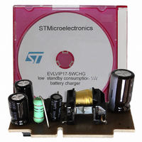
EVLVIP17-5WCHG
Description
BOARD EVAL FOR VIPER17
Manufacturer
STMicroelectronics
Series
VIPer™ plusr
Specifications of EVLVIP17-5WCHG
Main Purpose
AC/DC, Primary and Secondary Side
Outputs And Type
1, Isolated
Power - Output
5W
Voltage - Output
5.1V
Current - Output
1A
Voltage - Input
90 ~ 264VAC
Regulator Topology
Flyback
Frequency - Switching
115kHz
Board Type
Fully Populated
Utilized Ic / Part
TSM1052, VIPer17
Lead Free Status / RoHS Status
Lead free / RoHS Compliant
Other names
497-8250
Available stocks
Company
Part Number
Manufacturer
Quantity
Price


VIPER17
7.3
Power-up and soft-start up
If the input voltage rises up till the device start threshold, V
begins to grow due to the I
high voltage start up circuit. If the V
page
See
The IC is powered by the energy stored in the capacitor on the VDD pin, C
the self-supply circuit (typically an auxiliary winding of the transformer and a steering diode)
develops a voltage high enough to sustain the operation.
C
value higher than V
switching operation before the controller receives any energy from the auxiliary winding.
The following formula can be used for the V
Equation 1
The t
estimated by applicator according to the output stage configurations (transformer, output
capacitances, etc.).
During the converter start up time, the drain current limitation is progressively increased to
the maximum value. In this way the stress on the secondary diode is considerably reduced.
It also helps to prevent transformer saturation. The soft-start time lasts 8.5 ms and the
feature is implemented for every attempt of start up converter or after a fault.
Figure 22. I
VDD
Figure 23 on page
SSaux
6) the power MOSFET starts switching and the HV current generator is turned OFF.
capacitor must be sized enough to avoid fast discharge and keep the needed voltage
is the time needed for the steady state of the auxiliary voltage. This time is
I
DDch
DD
V
(-3 mA)
DRAIN
V
V
V
V
V
V
current during start-up and burst mode
FBbm
DDoff
V
FBolp
I
I
I
DDon
FBlin
DD
DD1
DD0
DD
START- UP
FB
DDoff
16.
threshold. In fact, a too low capacitance value could terminate the
DDch
NORMAL MODE
Doc ID 14419 Rev 7
current (see
C
DD
VDD
voltage reaches V
=
----------------------------------------
V
I
DD
DDch
DDon
Table 7 on page
capacitor calculation:
×
–
BURST MODE
t
V
SSaux
DDoff
DDon
DRAIN_START
6) coming from the internal
threshold (see
Operation descriptions
, the V
NORMAL MODE
VDD
t
t
t
t
V
FBbmhys
Table 7 on
DD
, until when
voltage
15/31
Related parts for EVLVIP17-5WCHG
Image
Part Number
Description
Manufacturer
Datasheet
Request
R

Part Number:
Description:
STMicroelectronics [RIPPLE-CARRY BINARY COUNTER/DIVIDERS]
Manufacturer:
STMicroelectronics
Datasheet:
Part Number:
Description:
STMicroelectronics [LIQUID-CRYSTAL DISPLAY DRIVERS]
Manufacturer:
STMicroelectronics
Datasheet:

Part Number:
Description:
BOARD EVAL FOR MEMS SENSORS
Manufacturer:
STMicroelectronics
Datasheet:
Part Number:
Description:
NPN TRANSISTOR POWER MODULE
Manufacturer:
STMicroelectronics
Datasheet:
Part Number:
Description:
TURBOSWITCH ULTRA-FAST HIGH VOLTAGE DIODE
Manufacturer:
STMicroelectronics
Datasheet:
Part Number:
Description:
Manufacturer:
STMicroelectronics
Datasheet:
Part Number:
Description:
DIODE / SCR MODULE
Manufacturer:
STMicroelectronics
Datasheet:
Part Number:
Description:
DIODE / SCR MODULE
Manufacturer:
STMicroelectronics
Datasheet:
Part Number:
Description:
Search -----> STE16N100
Manufacturer:
STMicroelectronics
Datasheet:
Part Number:
Description:
Search ---> STE53NA50
Manufacturer:
STMicroelectronics
Datasheet:
Part Number:
Description:
NPN Transistor Power Module
Manufacturer:
STMicroelectronics
Datasheet:
Part Number:
Description:
DIODE / SCR MODULE
Manufacturer:
STMicroelectronics
Datasheet: