MT9D131C12STCH ES Aptina LLC, MT9D131C12STCH ES Datasheet - Page 11
MT9D131C12STCH ES
Manufacturer Part Number
MT9D131C12STCH ES
Description
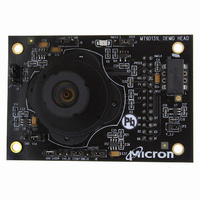
KIT HEAD BOARD FOR MT9D131
Manufacturer
Aptina LLC
Series
Micron®DigitalClarity®r
Datasheets
1.MT9P031I12STCH_ES.pdf
(6 pages)
2.MT9D131C12STCH_ES.pdf
(18 pages)
3.MT9D131C12STCH_ES.pdf
(2 pages)
Specifications of MT9D131C12STCH ES
Sensor Type
CMOS Imaging, Color (RGB)
Sensing Range
2 Megapixel
Interface
USB
Sensitivity
15 fps
Voltage - Supply
2.5 V ~ 3.1 V
Embedded
No
Utilized Ic / Part
MT9D131
Silicon Manufacturer
Aptina Imaging
Application Sub Type
Image Sensor
Kit Application Type
Sensing - Image / Light
Silicon Core Number
MT9D131
Kit Contents
Image Sensor And Lens
Lead Free Status / RoHS Status
Lead free / RoHS Compliant
Other names
557-1253
Q4051985
Q4051985


Output Interface
Control (Two-Wire Serial Interface)
Context and Operational Modes
Preview
Snapshot
Video
PDF: 09005aef824c90ce/Source: 09005aef824c90d6
MT9D131_LDS_2.fm - Rev. B 3/07 EN
Camera control and JPEG configuration/control are accomplished using a two-wire
serial interface. The interface supports individual access to all camera function registers
and JPEG control registers. In particular, all tables located in the JPEG quantization and
Huffman memories are accessible using the two-wire interface.
The MT9D131 can operate in several modes, including preview, still capture (snapshot),
and video. All modes of operation are individually configurable and are organized as two
contexts—context A and context B. A context is defined by sensor image size, frame rate,
resolution and other associated parameters. The user can switch between the two con-
texts by sending a command through the two-wire serial interface.
Context A is primarily intended for use in the preview mode. During preview, the sensor
usually outputs low resolution images at a relatively high frame rate, and its power con-
sumption is kept to a minimum. Context B can be configured for the still capture or
video mode, as required by the user. For still capture configuration, the user typically
specifies the desired output image size, if JPEG compression, how many frames to cap-
ture, and so on. For video, the user might select a different image size and a fixed frame
rate.
To take a snapshot, the user must send a command that changes the context from A to
context B. Typical sequence of events after this command is as follows. First, the camera
exposure and white balance is automatically adjusted to the changed illumination of the
scene. Next, the camera enables JPEG compression and capture one or more frames of
desired size. Completing the sequence, the camera automatically returns to context A
and resume running preview.
To start video capture, the user has to change relevant context B settings, such as cap-
ture mode, image size and frame rate, and again send a context change command. Upon
receiving it, the MT9D131 switches to the modified context B settings, while continuing
to output YUV-encoded image data. Auto exposure automatically switches to smooth
continuous operation. To exit the video capture mode, the user has to send another con-
text change command causing the sensor to switch back to context A.
MT9D131: 1/3.2-Inch 2-Mp SOC Digital Image Sensor
11
Micron Technology, Inc., reserves the right to change products or specifications without notice.
Architecture Overview
©2006 Micron Technology, Inc. All rights reserved.
Preliminary
Related parts for MT9D131C12STCH ES
Image
Part Number
Description
Manufacturer
Datasheet
Request
R

Part Number:
Description:
2M-Pixel CMOS Camera System on Chip
Manufacturer:
Micron
Datasheet:

Part Number:
Description:
SENSOR IMAGE VGA COLOR CMOS PLCC
Manufacturer:
Aptina LLC
Datasheet:

Part Number:
Description:
IC SENSOR IMAGE COLOR 48CLCC
Manufacturer:
Aptina LLC
Datasheet:

Part Number:
Description:
SENSOR IMAGE 1.3MP CMOS 48-CLCC
Manufacturer:
Aptina LLC
Datasheet:

Part Number:
Description:
SENSOR IMAGE 2MP CMOS 48-CLCC
Manufacturer:
Aptina LLC
Datasheet:

Part Number:
Description:
SENSOR IMAGE VGA MONO 52IBGA
Manufacturer:
Aptina LLC
Datasheet:

Part Number:
Description:
SENSOR IMAGE VGA COLOR 48CLCC
Manufacturer:
Aptina LLC
Datasheet:

Part Number:
Description:
SENSOR IMAGE COLOR CMOS 48-PLCC
Manufacturer:
Aptina LLC
Datasheet:

Part Number:
Description:
KIT HEAD BOARD FOR MT9P031
Manufacturer:
Aptina LLC
Datasheet:

Part Number:
Description:
KIT HEAD BOARD FOR MT9P031
Manufacturer:
Aptina LLC
Datasheet:
Part Number:
Description:
SENSOR IMAGE VGA COLOR CMOS PLCC
Manufacturer:
Aptina LLC
Datasheet:
Part Number:
Description:
IC SENSOR IMAGE COLOR 48CLCC
Manufacturer:
Aptina LLC
Datasheet:
Part Number:
Description:
SENSOR IMAGE 2MP CMOS 48-CLCC
Manufacturer:
Aptina LLC
Datasheet:
