MT9D131C12STCH ES Aptina LLC, MT9D131C12STCH ES Datasheet - Page 9
MT9D131C12STCH ES
Manufacturer Part Number
MT9D131C12STCH ES
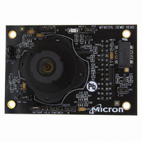
Description
KIT HEAD BOARD FOR MT9D131
Manufacturer
Aptina LLC
Series
Micron®DigitalClarity®r
Datasheets
1.MT9P031I12STCH_ES.pdf
(6 pages)
2.MT9D131C12STCH_ES.pdf
(18 pages)
3.MT9D131C12STCH_ES.pdf
(2 pages)
Specifications of MT9D131C12STCH ES
Sensor Type
CMOS Imaging, Color (RGB)
Sensing Range
2 Megapixel
Interface
USB
Sensitivity
15 fps
Voltage - Supply
2.5 V ~ 3.1 V
Embedded
No
Utilized Ic / Part
MT9D131
Silicon Manufacturer
Aptina Imaging
Application Sub Type
Image Sensor
Kit Application Type
Sensing - Image / Light
Silicon Core Number
MT9D131
Kit Contents
Image Sensor And Lens
Lead Free Status / RoHS Status
Lead free / RoHS Compliant
Other names
557-1253
Q4051985
Q4051985


Color Correction and Aperture Correction
Gamma Correction
YUV Processing
Image Cropping and Decimation
PDF: 09005aef824c90ce/Source: 09005aef824c90d6
MT9D131_LDS_2.fm - Rev. B 3/07 EN
To achieve good color fidelity of IFP output, interpolated RGB values of all pixels are
subjected to color correction. The IFP multiplies each vector of three pixel colors by a
3 x 3 color correction matrix. The three components of the resulting color vector are all
sums of three 10-bit numbers. Since such sums can have up to 12 significant bits, the bit
width of the image data stream is widened to 12 bits per color (36 bits per pixel). The
color correction matrix can be either programmed by the user or automatically selected
by the auto white balance (AWB) algorithm implemented in the IFP. Color correction
should ideally produce output colors that are independent of the spectral sensitivity and
color cross-talk characteristics of the image sensor. The optimal values of color correc-
tion matrix elements depend on those sensor characteristics and on the spectrum of
light incident on the sensor.
To increase image sharpness, a programmable aperture correction is applied to color
corrected image data, equally to each of the 12-bit R, G, and B color channels.
Like the aperture correction, gamma correction is applied equally to each of the 12-bit R,
G, and B color channels. Gamma correction curve is implemented as a piecewise linear
function with 19 knee points, taking 12-bit arguments and mapping them to 8-bit out-
put. The driver variables include two arrays of knee point ordinates defining two sepa-
rate gamma curves for sensor operation contexts A and B.
After the gamma correction, the image data stream undergoes RGB to YUV conversion
and optionally further corrective processing. The first step in this processing is removal
of highlight coloration, also referred to as “color kill.” It affects only pixels whose bright-
ness exceeds a certain pre-programmed threshold. The U and V values of those pixels
are attenuated proportionally to the difference between their brightness and the thresh-
old.
To ensure that the size of images output by MT9D131 can be tailored to the needs of all
users, the IFP includes a decimator module. When enabled, this module performs “dec-
imation” of incoming images, that is, shrinks them to arbitrarily selected width and
height without reducing the field of view and without discarding any pixel values. The
latter point merits underscoring, because the terms “decimator” and “image decima-
tion” suggest image size reduction by deleting columns and/or rows at regular intervals.
Despite the terminology, no such deletions take place in the decimator module. Instead,
it performs “pixel binning,” that is, divides each input image into rectangular bins corre-
sponding to individual pixels of the desired output image, averages pixel values in these
bins,and assembles the output image from the bin averages. Pixels lying on bin bound-
aries contribute to more than one bin average: their values are added to bin-wide sums
of pixel values with fractional weights. The entire procedure preserves all image infor-
mation that can be included in the downsized output image and filters out high-fre-
quency features that could cause aliasing.
The image decimation in the IFP can be preceded by image cropping and/or image dec-
imation in the sensor core. Image cropping takes place when the sensor core is pro-
grammed to output pixel values from a rectangular portion of its pixel array - a window -
smaller than the default 1600 x 1200 window. Pixels outside the selected cropping win-
dow are not read out, which results in narrower field of view than at the default sensor
settings. Irrespective of the size and position of the cropping window, the MT9D131 sen-
sor core can also decimate outgoing images by skipping columns and/or rows of the
MT9D131: 1/3.2-Inch 2-Mp SOC Digital Image Sensor
9
Micron Technology, Inc., reserves the right to change products or specifications without notice.
Architecture Overview
©2006 Micron Technology, Inc. All rights reserved.
Preliminary
Related parts for MT9D131C12STCH ES
Image
Part Number
Description
Manufacturer
Datasheet
Request
R

Part Number:
Description:
2M-Pixel CMOS Camera System on Chip
Manufacturer:
Micron
Datasheet:

Part Number:
Description:
SENSOR IMAGE VGA COLOR CMOS PLCC
Manufacturer:
Aptina LLC
Datasheet:

Part Number:
Description:
IC SENSOR IMAGE COLOR 48CLCC
Manufacturer:
Aptina LLC
Datasheet:

Part Number:
Description:
SENSOR IMAGE 1.3MP CMOS 48-CLCC
Manufacturer:
Aptina LLC
Datasheet:

Part Number:
Description:
SENSOR IMAGE 2MP CMOS 48-CLCC
Manufacturer:
Aptina LLC
Datasheet:

Part Number:
Description:
SENSOR IMAGE VGA MONO 52IBGA
Manufacturer:
Aptina LLC
Datasheet:

Part Number:
Description:
SENSOR IMAGE VGA COLOR 48CLCC
Manufacturer:
Aptina LLC
Datasheet:

Part Number:
Description:
SENSOR IMAGE COLOR CMOS 48-PLCC
Manufacturer:
Aptina LLC
Datasheet:

Part Number:
Description:
KIT HEAD BOARD FOR MT9P031
Manufacturer:
Aptina LLC
Datasheet:

Part Number:
Description:
KIT HEAD BOARD FOR MT9P031
Manufacturer:
Aptina LLC
Datasheet:
Part Number:
Description:
SENSOR IMAGE VGA COLOR CMOS PLCC
Manufacturer:
Aptina LLC
Datasheet:
Part Number:
Description:
IC SENSOR IMAGE COLOR 48CLCC
Manufacturer:
Aptina LLC
Datasheet:
Part Number:
Description:
SENSOR IMAGE 2MP CMOS 48-CLCC
Manufacturer:
Aptina LLC
Datasheet:
