MT9D131C12STCH ES Aptina LLC, MT9D131C12STCH ES Datasheet - Page 8
MT9D131C12STCH ES
Manufacturer Part Number
MT9D131C12STCH ES
Description
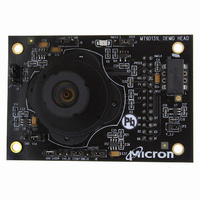
KIT HEAD BOARD FOR MT9D131
Manufacturer
Aptina LLC
Series
Micron®DigitalClarity®r
Datasheets
1.MT9P031I12STCH_ES.pdf
(6 pages)
2.MT9D131C12STCH_ES.pdf
(18 pages)
3.MT9D131C12STCH_ES.pdf
(2 pages)
Specifications of MT9D131C12STCH ES
Sensor Type
CMOS Imaging, Color (RGB)
Sensing Range
2 Megapixel
Interface
USB
Sensitivity
15 fps
Voltage - Supply
2.5 V ~ 3.1 V
Embedded
No
Utilized Ic / Part
MT9D131
Silicon Manufacturer
Aptina Imaging
Application Sub Type
Image Sensor
Kit Application Type
Sensing - Image / Light
Silicon Core Number
MT9D131
Kit Contents
Image Sensor And Lens
Lead Free Status / RoHS Status
Lead free / RoHS Compliant
Other names
557-1253
Q4051985
Q4051985


Black Level Conditioning and Digital Gain
Lens Shading Correction
Line Buffers
Defect Correction
Color Interpolation and Edge Detection
PDF: 09005aef824c90ce/Source: 09005aef824c90d6
MT9D131_LDS_2.fm - Rev. B 3/07 EN
Image stream processing starts with black level conditioning and multiplication of all
pixel values by a programmable digital gain.
Inexpensive lenses tend to produce images whose brightness is significantly attenuated
near the edges. Chromatic aberration in such lenses can cause color variation across the
field of view. There are also other factors causing fixed-pattern signal gradients in
images captured by image sensors. The cumulative result of all these factors is known as
lens shading. The MT9D131 has an embedded lens shading correction (LC) module that
can be programmed to precisely counter the shading effect of a lens on each RGB color
signal. The LC module multiplies RGB signals by a 2-dimensional correction function
F(x,y), whose profile in both x and y direction is a piecewise quadratic polynomial with
coefficients independently programmable for each direction and color.
Several data processing steps following the lens shading correction require access to
pixel values from up to 8 consecutive image lines. For these lines to be simultaneously
available for processing, they must be buffered. The IFP includes a number of SRAM line
buffers that are used to perform defect correction, color interpolation, image decima-
tion, and JPEG encoding.
The IFP performs on-the-fly defect correction that can mask pixel array defects such as
high-dark-current (“hot”) pixels and pixels that are darker or brighter than their neigh-
bors due to photoresponse nonuniformity. The defect correction algorithm uses several
pixel features to distinguish between normal and defective pixels. After identifying the
latter, it replaces their actual values with values inferred from the values of nearest
same-color neighbors.
In the raw data stream fed by the sensor core to the IFP, each pixel is represented by a
10-bit integer number, which, to make things simple, can be considered proportional to
the pixel’s response to a one-color light stimulus—red, green, or blue—depending on
the pixel’s position under the color filter array. Initial data processing steps, up to and
including the defect correction, preserve the one-color-per-pixel nature of the data
stream, but after the defect correction it must be converted to a three-colors-per-pixel
stream appropriate for standard color processing. The conversion is done by an edge-
sensitive color interpolation module. The module pads the incomplete color informa-
tion available for each pixel with information extracted from an appropriate set of
neighboring pixels. The algorithm used to select this set and extract the information
seeks the best compromise between maintaining the sharpness of the image and filter-
ing out high-frequency noise. The simplest interpolation algorithm is to sort the nearest
eight neighbors of every pixel into three sets—red, green, and blue, discard the set of
pixels of the same color as the center pixel (if there are any), calculate average pixel val-
ues for the remaining two sets, and use the averages instead of the missing color data for
the center pixel. Such averaging reduces high-frequency noise, but it also blurs and dis-
torts sharp transitions (edges) in the image. To avoid this problem, the interpolation
module performs edge detection in the neighborhood of every processed pixel and,
depending on its results, extracts color information from neighboring pixels in a number
of different ways. In effect, it does low-pass filtering in flat-field image areas and avoids
doing it near edges.
MT9D131: 1/3.2-Inch 2-Mp SOC Digital Image Sensor
8
Micron Technology, Inc., reserves the right to change products or specifications without notice.
Architecture Overview
©2006 Micron Technology, Inc. All rights reserved.
Preliminary
Related parts for MT9D131C12STCH ES
Image
Part Number
Description
Manufacturer
Datasheet
Request
R

Part Number:
Description:
2M-Pixel CMOS Camera System on Chip
Manufacturer:
Micron
Datasheet:

Part Number:
Description:
SENSOR IMAGE VGA COLOR CMOS PLCC
Manufacturer:
Aptina LLC
Datasheet:

Part Number:
Description:
IC SENSOR IMAGE COLOR 48CLCC
Manufacturer:
Aptina LLC
Datasheet:

Part Number:
Description:
SENSOR IMAGE 1.3MP CMOS 48-CLCC
Manufacturer:
Aptina LLC
Datasheet:

Part Number:
Description:
SENSOR IMAGE 2MP CMOS 48-CLCC
Manufacturer:
Aptina LLC
Datasheet:

Part Number:
Description:
SENSOR IMAGE VGA MONO 52IBGA
Manufacturer:
Aptina LLC
Datasheet:

Part Number:
Description:
SENSOR IMAGE VGA COLOR 48CLCC
Manufacturer:
Aptina LLC
Datasheet:

Part Number:
Description:
SENSOR IMAGE COLOR CMOS 48-PLCC
Manufacturer:
Aptina LLC
Datasheet:

Part Number:
Description:
KIT HEAD BOARD FOR MT9P031
Manufacturer:
Aptina LLC
Datasheet:

Part Number:
Description:
KIT HEAD BOARD FOR MT9P031
Manufacturer:
Aptina LLC
Datasheet:
Part Number:
Description:
SENSOR IMAGE VGA COLOR CMOS PLCC
Manufacturer:
Aptina LLC
Datasheet:
Part Number:
Description:
IC SENSOR IMAGE COLOR 48CLCC
Manufacturer:
Aptina LLC
Datasheet:
Part Number:
Description:
SENSOR IMAGE 2MP CMOS 48-CLCC
Manufacturer:
Aptina LLC
Datasheet:
