AT91SAM7A3-EK Atmel, AT91SAM7A3-EK Datasheet - Page 15
AT91SAM7A3-EK
Manufacturer Part Number
AT91SAM7A3-EK
Description
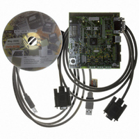
KIT EVAL FOR AT91SAM7A3
Manufacturer
Atmel
Series
AT91SAM Smart ARMr
Type
MCUr
Datasheet
1.AT91SAM7A3-EK.pdf
(25 pages)
Specifications of AT91SAM7A3-EK
Contents
Evaluation Board, Parallel Cable and CD-ROM
Silicon Manufacturer
Atmel
Core Architecture
ARM
Core Sub-architecture
ARM7TDMI
Silicon Core Number
AT91SAM7A3
Silicon Family Name
ARM
Kit Contents
Board CD Docs
Rohs Compliant
Yes
For Use With/related Products
AT91SAM7A3
Lead Free Status / RoHS Status
Lead free / RoHS Compliant


4.1
AT91SAM7A3-EK Evaluation Board User Guide
Configuration
Straps
Table 4-1. Configuration Jumpers and Straps
Designation
J13
J14
J15
J16
J17
J18
J19
J20
J21
J22
J23
J24
J25
J26
Opened
Opened
Opened
Opened
Default
Setting
Closed
Closed
Closed
Closed
Closed
Closed
Closed
Open
2-3
1-2
VDD3V3 Jumper
VDDPLL Jumper
VDDANA Jumper
VDDBU Jumper select
1-2 : Optional Lithium Thionyl Chloride 3.6V Backup
Battery
2-3 : 3.3V power
ADVREFP Jumper select
1-2 : 3.00V Voltage reference
2-3 : VDDANA
Enables 120 ohms CAN bus resistance termination
(CAN0)
Enables 5V power supply for TJA1050 Transceiver. It is
closed by wire on solder side. J19 and J20 should not be
closed at the same time.
Disables 3.3V power supply for TJA1050 Transceiver. J20
and J19 should not be closed at the same time.
Enables 120 ohms CAN bus resistance termination
(CAN1)
Enables 5V power supply for TJA1050 Transceiver. It is
closed by wire on solder side. J22 and J23 should not be
closed at the same time.
Disables 3.3V power supply for TJA1050 Transceiver. J23
and J22 should not be closed at the same time.
Do not use: Factory test mode
Select ICE mode or JTAG mode (Closed)
External XIN clock input. S8 and S9 must be open.
Configuration Straps
(1)
(1)
(1)
(1)
Feature
(1)
Section 4
6165C–ATARM–26-Jun-06
4-1
Related parts for AT91SAM7A3-EK
Image
Part Number
Description
Manufacturer
Datasheet
Request
R

Part Number:
Description:
MCU ARM9 64K SRAM 144-LFBGA
Manufacturer:
Atmel
Datasheet:

Part Number:
Description:
IC ARM7 MCU FLASH 256K 100LQFP
Manufacturer:
Atmel
Datasheet:

Part Number:
Description:
IC ARM9 MPU 217-LFBGA
Manufacturer:
Atmel
Datasheet:
Part Number:
Description:
MCU ARM9 ULTRA LOW PWR 217-LFBGA
Manufacturer:
Atmel
Datasheet:

Part Number:
Description:
MCU ARM9 324-TFBGA
Manufacturer:
Atmel
Datasheet:
Part Number:
Description:
IC MCU ARM9 SAMPLING 217CBGA
Manufacturer:
Atmel
Datasheet:
Part Number:
Description:
IC ARM9 MCU 217-LFBGA
Manufacturer:
Atmel
Datasheet:

Part Number:
Description:
IC ARM9 MCU 208-PQFP
Manufacturer:
Atmel
Datasheet:
Part Number:
Description:
MCU ARM 512K HS FLASH 100-LQFP
Manufacturer:
Atmel
Datasheet:

Part Number:
Description:
MCU ARM 512K HS FLASH 100-TFBGA
Manufacturer:
Atmel
Datasheet:
Part Number:
Description:
IC ARM9 MCU 200 MHZ 324-TFBGA
Manufacturer:
Atmel
Datasheet:

Part Number:
Description:
IC ARM MCU 16BIT 128K 256BGA
Manufacturer:
Atmel
Datasheet:

Part Number:
Description:
IC ARM7 MCU 32BIT 128K 64LQFP
Manufacturer:
Atmel
Datasheet:

Part Number:
Description:
IC ARM7 MCU FLASH 256K 128-LQFP
Manufacturer:
Atmel
Datasheet:
Part Number:
Description:
IC ARM7 MCU FLASH 512K 128-LQFP
Manufacturer:
Atmel
Datasheet: