AT91SAM7A1-EK Atmel, AT91SAM7A1-EK Datasheet
AT91SAM7A1-EK
Specifications of AT91SAM7A1-EK
Available stocks


Related parts for AT91SAM7A1-EK


AT91SAM7A1-EK Summary of contents
Page 1
... AT91SAM7A1-EK Evaluation Board .............................................................................................. User Guide ...
Page 2
... AT91SAM7A1-EK Evaluation Board User Guide ...
Page 3
... Table of Contents Section 1 Overview............................................................................................... 1-1 1.1 Scope ........................................................................................................1-1 1.2 Deliverables ..............................................................................................1-1 1.3 AT91SAM7A1 Evaluation Board ...............................................................1-1 Section 2 Setting Up the AT91SAM7A1-EK Evaluation Board ............................. 2-1 2.1 Requirements............................................................................................2-1 2.2 Electrostatic Warning ................................................................................2-1 2.3 Layout .......................................................................................................2-1 2.4 Voltage ......................................................................................................2-2 2.5 Powering Up the Board .............................................................................2-2 2 ...
Page 4
... Table of Contents ii 6114A–ATARM–09/04 AT91SAM7A1-EK Evaluation Board User Guide ...
Page 5
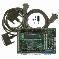
... Deliverables 1.3 AT91SAM7A1 Evaluation Board AT91SAM7A1-EK Evaluation Board User Guide The AT91SAM7A1-EK Evaluation Board enables real-time code development and evalu- ation. It supports the AT91SAM7A1 microcontroller. The evaluation board is supplied with: an AT91SAM7A1 evaluation board called the AT91SAM7A1-EK a bare power lead, a fuse, 2 jumpers ...
Page 6
... Diode bridge – Adjustable voltage regulators Clocks – 6 MHz and 32.768 KHz crystals Expansion connectors – Most chip I/Os accessible via two 50-pin connectors (J17, J18) – EBI expansion connector allowing plug-in of memory board or Ethernet board AT91SAM7A1-EK Evaluation Board User Guide ...
Page 7
... Layout AT91SAM7A1-EK Evaluation Board User Guide Setting Up the AT91SAM7A1-EK In order to set up the AT91SAM7A1-EK Evaluation Board, the following elements are required: the AT91SAM7A1-EK Evaluation Board itself a DC power supply capable of supplying 7V to 12V @ 400 mA (not supplied) The AT91SAM7A1-EK Evaluation Board is shipped in protective anti-static packaging. ...
Page 8
... AT91SAM7A1 device. Table 2-1. Current Consumption Measurement Procedure Block to Measure Core Analog Cells I/O Cells Positive (+) or Negative(-) Switch off, check the No fuse and the power supply connections Strap to Unsolder E1 Connect an ammeter in place E2 of the strap E3 AT91SAM7A1-EK Evaluation Board User Guide Action ...
Page 9
... AT91SAM7A1-EK Block Diagram Figure 2-4. AT91SAM7A1-EK Evaluation Board Block Diagram JTAG Connector ICE Embedded Connector 32.768 kHz Crystal Button DB9 CAN Connector Driver Buzzer Contrast Control LCD AT91SAM7A1-EK Evaluation Board User Guide AT91SAM7A1 Microcontroller Embedded ARM7TDMI ICE Core Osc AMBA ...
Page 10
... AT91SAM7A1-EK Evaluation Board User Guide ...
Page 11
... Power Supply Block AT91SAM7A1-EK Evaluation Board User Guide The AT91SAM7A1-EK evaluation board consists of eight main blocks. Each block is described in the sections that follow. The block diagram is shown in Figure 2-4. The processor is based on an ARM7TDMI Standard modules (e.g., timers and USART) Specific modules (e ...
Page 12
... Displays 2 lines of 16 characters each. The LCD is driven by the PIO which can be powered by 3V3 or 5V. The LCD tolerates these two voltages. Users can display messages on the LCD. The contrast voltage is provided by the PWM1 and can be measured by ADC0 channel AT91SAM7A1-EK Evaluation Board User Guide ...
Page 13
... The recommended CAN bus load is 60 Ohm. Depending on the external input bus resistor, users can disconnect resistors to achieve the correct bus load. For more details, refer to Figure 4-5. Via USART modules, the AT91SAM7A1-EK board provides the following: 2 LIN buses and 1 RS-232 line or ...
Page 14
... RX (Receive Data) TX (Transmit Data) Ground Not connected Not connected Function AT91SAM7A1 Pin CD (Carrier Detect) RX (Receive Data) TX (Transmit Data) Ground DSR (Data Set Ready) CTS (Clear to Send) RI (Ring Indicator) AT91SAM7A1-EK Evaluation Board User Guide Open Straps No strap E9 E16 E16 E5 E6 (1) RXD0 TXD0 GND (1) ...
Page 15
... Oscillators and Clock Distribution 3.8 Memory Organization AT91SAM7A1-EK Evaluation Board User Guide Note: Depending on the strap configuration, either SubD9 pin can be controlled by UPIO or by USART0 pins. The schematic of these connectors is the same as the one used by the CAN0 module (see Section 3.5). ...
Page 16
... On-board Flash address line 20 is driven. User can access the whole memory space. On-board Flash upper memory protected. User can access only the 1 Mbyte lower space. On-board Flash lower memory protected. User can access only the 1 Mbyte upper space. AT91SAM7A1-EK Evaluation Board User Guide ...
Page 17
... ICE Interface 3.12 Default Strap Configuration AT91SAM7A1-EK Evaluation Board User Guide ® An ARM -standard 20-pin box header (J11) is provided to enable connection of an ICE interface to the JTAG inputs on the AT91SAM7A1 device. This allows code to be devel- oped on the board without the use of system resources such as memory and serial ports ...
Page 18
... AT91SAM7A1-EK Evaluation Board User Guide ...
Page 19
... Schematics AT91SAM7A1-EK Evaluation Board User Guide Table 4-1. AT91SAM7A1 Schematics Figure Reference Figure 4-1 Figure 4-2 Figure 4-3 Figure 4-4 Figure 4-5 Figure 4-6 Figure 4-7 Figure 4-8 Figure 4-9 Figure 4-10 Section 4 Schematics Denomination Top Level Layout AT91SAM7A1 Power ...
Page 20
... Figure 4-1. Components Side Assembly 4-2 6114A–ATARM–09/04 AT91SAM7A1-EK Evaluation Board User Guide ...
Page 21
... Figure 4-2. AT91SAM7A1 AT91SAM7A1-EK Evaluation Board User Guide 4-3 6114A–ATARM–09/04 ...
Page 22
... Figure 4-3. Power 4-4 6114A–ATARM–09/04 AT91SAM7A1-EK Evaluation Board User Guide ...
Page 23
... Figure 4-4. Application Interface AT91SAM7A1-EK Evaluation Board User Guide 4-5 6114A–ATARM–09/04 ...
Page 24
... Figure 4-5. CAN Interface 4-6 6114A–ATARM–09/04 AT91SAM7A1-EK Evaluation Board User Guide ...
Page 25
... Figure 4-6. RS-232 and LIN Interfaces AT91SAM7A1-EK Evaluation Board User Guide 4-7 6114A–ATARM–09/04 ...
Page 26
... Figure 4-7. ICE Interface 4-8 6114A–ATARM–09/04 AT91SAM7A1-EK Evaluation Board User Guide ...
Page 27
... Figure 4-8. Memories Note: 1. AT479BV1614A-90TC can be replaced by AT49BV162A. AT91SAM7A1-EK Evaluation Board User Guide (1) 4-9 6114A–ATARM–09/04 ...
Page 28
... Figure 4-9. EBI Expansion 4-10 6114A–ATARM–09/04 AT91SAM7A1-EK Evaluation Board User Guide ...
Page 29
... Figure 4-10. Expansion Connector AT91SAM7A1-EK Evaluation Board User Guide 4-11 6114A–ATARM–09/04 ...
Page 30
... AT91SAM7A1-EK Evaluation Board User Guide ...
Page 31
... No licenses to patents or other intellectual property of Atmel are granted by the Company in connection with the sale of Atmel products, expressly or by implication. Atmel’s products are not authorized for use as critical components in life support devices or systems. ...