ATICE50 Atmel, ATICE50 Datasheet - Page 26
ATICE50
Manufacturer Part Number
ATICE50
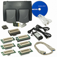
Description
EMULATOR IN CIRCUIT MEGAAVR
Manufacturer
Atmel
Specifications of ATICE50
Lead Free Status / RoHS Status
Contains lead / RoHS non-compliant


2523A–AVR–11/02
General Description
3.5.2
3-12
Digital I/O
The Digital IO ports of the ICE50 are realized as shown in Figure 3-17 using CMOS buff-
ers and voltage converters.
Figure 3-17. Digital I/O
The propagation delay of the IO ports are larger for the ICE50 than for the actual emu-
lated part. The diagram below shows the timing data for driving out and reading in a
signal on the IO ports of the Emulator. The data direction register is assumed set to “1”
in Figure 3-18. Table 3-3 shows typical data.
Figure 3-18. Data Direction Register
PULLUP (DDRxy & PORTxy)
DDRxy
PORTxy
PINxy
PINKEEPx
PORTxy
PINxy
Pxy
V
CC
Emulator
LEVEL CONVERTER
DIGITAL I/O
t
OHL
V
t
IHL
CC
Target
V
CC
330K
t
OLH
t
ILH
ICE50 User Guide
36K
Pxy
Related parts for ATICE50
Image
Part Number
Description
Manufacturer
Datasheet
Request
R

Part Number:
Description:
DEV KIT FOR AVR/AVR32
Manufacturer:
Atmel
Datasheet:

Part Number:
Description:
INTERVAL AND WIPE/WASH WIPER CONTROL IC WITH DELAY
Manufacturer:
ATMEL Corporation
Datasheet:
Part Number:
Description:
Low-Voltage Voice-Switched IC for Hands-Free Operation
Manufacturer:
ATMEL Corporation
Datasheet:
Part Number:
Description:
MONOLITHIC INTEGRATED FEATUREPHONE CIRCUIT
Manufacturer:
ATMEL Corporation
Datasheet:
Part Number:
Description:
AM-FM Receiver IC U4255BM-M
Manufacturer:
ATMEL Corporation
Datasheet:
Part Number:
Description:
Monolithic Integrated Feature Phone Circuit
Manufacturer:
ATMEL Corporation
Datasheet:
Part Number:
Description:
Multistandard Video-IF and Quasi Parallel Sound Processing
Manufacturer:
ATMEL Corporation
Datasheet:
Part Number:
Description:
High-performance EE PLD
Manufacturer:
ATMEL Corporation
Datasheet:
Part Number:
Description:
8-bit Flash Microcontroller
Manufacturer:
ATMEL Corporation
Datasheet:
Part Number:
Description:
2-Wire Serial EEPROM
Manufacturer:
ATMEL Corporation
Datasheet: