ATICE50 Atmel, ATICE50 Datasheet - Page 31
ATICE50
Manufacturer Part Number
ATICE50
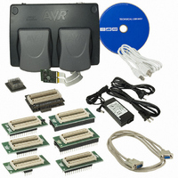
Description
EMULATOR IN CIRCUIT MEGAAVR
Manufacturer
Atmel
Specifications of ATICE50
Lead Free Status / RoHS Status
Contains lead / RoHS non-compliant


3.7
3.7.1
ICE50 User Guide
Probe
Description
Probe Description
The ICE50 probe is the link between the flex cable going out from the POD and the Per-
sonaliy Adapter that fits into the target application. The main purpose of the probe is to
route all the signals from the flex cable to the appropriate pins of the personality adapter.
In addition the Probe implements current limitation on all the I/O pins in order to protect
both the target and the POD. The probe also implements proper line termination in order
to avoid ringing on high freuency signals.
The Probe contains clock driver circuitry for the ICE50, voltage polarity and short circuit
protection. Figure 3-23 show a picture of the probe and a simplified block diagram of
how the clock driver circuitry is implemented is shown in Figure 3-24 and Figure 3-25.
By putting the clock driver circuitry on the Probe (as close as possible to the target
board) the best possible emulation of the AVR clock options are achieved.
Figure 3-23. Probe
Figure 3-24. Timer Oscillator
Enable
Output
Oscillator
Timer
Drive
General Description
2523A–AVR–11/02
3-17
Related parts for ATICE50
Image
Part Number
Description
Manufacturer
Datasheet
Request
R

Part Number:
Description:
DEV KIT FOR AVR/AVR32
Manufacturer:
Atmel
Datasheet:

Part Number:
Description:
INTERVAL AND WIPE/WASH WIPER CONTROL IC WITH DELAY
Manufacturer:
ATMEL Corporation
Datasheet:
Part Number:
Description:
Low-Voltage Voice-Switched IC for Hands-Free Operation
Manufacturer:
ATMEL Corporation
Datasheet:
Part Number:
Description:
MONOLITHIC INTEGRATED FEATUREPHONE CIRCUIT
Manufacturer:
ATMEL Corporation
Datasheet:
Part Number:
Description:
AM-FM Receiver IC U4255BM-M
Manufacturer:
ATMEL Corporation
Datasheet:
Part Number:
Description:
Monolithic Integrated Feature Phone Circuit
Manufacturer:
ATMEL Corporation
Datasheet:
Part Number:
Description:
Multistandard Video-IF and Quasi Parallel Sound Processing
Manufacturer:
ATMEL Corporation
Datasheet:
Part Number:
Description:
High-performance EE PLD
Manufacturer:
ATMEL Corporation
Datasheet:
Part Number:
Description:
8-bit Flash Microcontroller
Manufacturer:
ATMEL Corporation
Datasheet:
Part Number:
Description:
2-Wire Serial EEPROM
Manufacturer:
ATMEL Corporation
Datasheet: