ATICE50 Atmel, ATICE50 Datasheet - Page 29
ATICE50
Manufacturer Part Number
ATICE50
Description
EMULATOR IN CIRCUIT MEGAAVR
Manufacturer
Atmel
Specifications of ATICE50
Lead Free Status / RoHS Status
Contains lead / RoHS non-compliant


3.6
3.6.1
3.6.2
ICE50 User Guide
Power System
Description
Power Supply
ICE50 Power System The ICE50 has an internal power regulator designed to deliver regulated voltages for
The ADC is built using analog multiplexers, programmable gain instrumentation amplifi-
ers and a 10-bit successive approximation A/D converter. This construction should have
the same performance as the actual part, but since the ADC is located on the POD as
an external construction the analog components will be more susceptible to ambient
noise and noise from switching IO lines.
Note:
All inputs to the ADC have serial current limiting resistors of 330 . This is to protect the
inputs of the ADC circuit when the emulator is switched off and the target power is
present. The outputs of the input multiplexers are clamped to V
when target V
of approximately (Vinput - 0.3V)/330 through each ADC input pin.
The ICE50 needs external power in order to function. A switching power adapter is sup-
plied with the unit. The power adapter will accept input voltages in the range of 100VAC
to 240VAC and frequencies from 50Hz to 60Hz. This will cover most situations.
Figure 3-22. Power Supply
The power supply delivered with ICE50 is dimensioned to meet the requirements of the
Emulator. If another power supply is used, it should supply a voltage between 9 and 15
VDC, and a minimum of 20W. It connects to the main unit through a standard connector
with 2.1 mm center tap. Ground is connected to the center tap.
use by the ICE itself. The power system is not designed to provide external power to the
target application.
Internal analog reference voltage is set to 2.5 volt when using the emulator. This
differs from part which uses 2.56 V. Due to this fact ADC conversions done by
the emulator using the internal analog reference voltage differ from the conver-
sions done in part.
CC
is present and the emulator power is turned off there will flow a current
CC
General Description
and GND and thus
2523A–AVR–11/02
3-15
Related parts for ATICE50
Image
Part Number
Description
Manufacturer
Datasheet
Request
R

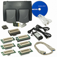
Part Number:
Description:
DEV KIT FOR AVR/AVR32
Manufacturer:
Atmel
Datasheet:

Part Number:
Description:
INTERVAL AND WIPE/WASH WIPER CONTROL IC WITH DELAY
Manufacturer:
ATMEL Corporation
Datasheet:
Part Number:
Description:
Low-Voltage Voice-Switched IC for Hands-Free Operation
Manufacturer:
ATMEL Corporation
Datasheet:
Part Number:
Description:
MONOLITHIC INTEGRATED FEATUREPHONE CIRCUIT
Manufacturer:
ATMEL Corporation
Datasheet:
Part Number:
Description:
AM-FM Receiver IC U4255BM-M
Manufacturer:
ATMEL Corporation
Datasheet:
Part Number:
Description:
Monolithic Integrated Feature Phone Circuit
Manufacturer:
ATMEL Corporation
Datasheet:
Part Number:
Description:
Multistandard Video-IF and Quasi Parallel Sound Processing
Manufacturer:
ATMEL Corporation
Datasheet:
Part Number:
Description:
High-performance EE PLD
Manufacturer:
ATMEL Corporation
Datasheet:
Part Number:
Description:
8-bit Flash Microcontroller
Manufacturer:
ATMEL Corporation
Datasheet:
Part Number:
Description:
2-Wire Serial EEPROM
Manufacturer:
ATMEL Corporation
Datasheet: