MCB2100+U NXP Semiconductors, MCB2100+U Datasheet
MCB2100+U
Specifications of MCB2100+U
OM10046


Related parts for MCB2100+U


MCB2100+U Summary of contents
Page 1
AN10302 Using the Philips LPC2000 Flash utility with the Keil MCB2100 and IAR LPC210x Kickstart evaluation boards Rev. 04 — 12 October 2006 Document information Info Content Keywords LPC2000, Flash utility, Keil MCB2100, IAR LPC210x Abstract Application information for the ...
Page 2
... NXP Semiconductors Revision history Rev Date Description 04 20061012 Fourth version • 03 20040610 Third version 02 20040512 Second version 01 20040430 Initial version Contact information For additional information, please visit: For sales office addresses, please send an email to: AN10302_4 Application note Updated Figure 2. http://www.nxp.com salesaddresses@nxp.com Rev. 04 — ...
Page 3
... NXP Semiconductors 1. Introduction In-System programming (ISP method of programming and erasing the on-chip flash or RAM memory using the boot loader software and a serial port. The part may reside in the end-user system. The flash boot loader provides an In-System Programming interface for programming the on-chip flash or RAM memory. This boot loader is located in the upper flash memory, it can be read but not written to or erased ...
Page 4
... NXP Semiconductors Fig 1. Boot process flowchart. AN10302_4 Application note Using the Philips LPC2000 Flash utility Rev. 04 — 12 October 2006 AN10302 © NXP B.V. 2006. All rights reserved ...
Page 5
... NXP Semiconductors 3. Details of the Philips LPC2000 Flash utility This flash utility is available for free download from the Philips website. This software, in combination with the hardware described below, allows for hands-off erasure, uploading, and execution of code. The Philips LPC2000 Flash utility utilizes two, otherwise unused, signals (RTS and DTR) of the PC serial port to control the microcontroller reset and P0 ...
Page 6
... NXP Semiconductors Fig 3. Flash Utility main screen. The main screen of the Flash Utility provides access to most if its functionality. When the “use DTR/RTS…” box (1) is checked then control of reset and P0.14 is done by the utility as described above. If this box is unchecked then ISP mode must be entered manually. If the “ ...
Page 7
... NXP Semiconductors Fig 4. Flash buffer screen. 3.4 RAM buffer operations Ram buffer operations (accessible from the “buffer” pull-down menu) are similar to flash buffer operations including the uploading of HEX files etc. AN10302_4 Application note Using the Philips LPC2000 Flash utility Rev. 04 — 12 October 2006 AN10302 © ...
Page 8
... NXP Semiconductors Fig 5. RAM buffer operations. AN10302_4 Application note Using the Philips LPC2000 Flash utility Rev. 04 — 12 October 2006 AN10302 © NXP B.V. 2006. All rights reserved ...
Page 9
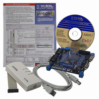
... NXP Semiconductors 4. Hardware 4.1 Keil MCB2100 evaluation board Figure 6 shows an overview of the Keil MCB2100 evaluation board. Fig 6. Keil MCB2100 evaluation board overview. JTAG port — Connection to JTAG emulator (e.g. Keil ULink). This is a standard JTAG port as outlined in ARM documentation. ETM (Embedded Trace Macrocell) port — Provides interface to emulators with trace capability. P3 and P4, CAN ports — ...
Page 10
... NXP Semiconductors LEDs — buffered with a 74LVC octal buffer, enabled by J6. Potentiometer — Configured as a voltage divider with its output connected to AIN0 via jumper J2. Table 1. Jumper J1 J2 [ [2] J10 [1] These jumpers supply the voltages to the microcontroller and must be in for normal operation. ...
Page 11
... NXP Semiconductors Fig 7. IAR/Philips LPC210x Kickstart card. JTAG port — Connection to JTAG emulator (e.g. JLink). This is a standard JTAG port as outlined in ARM documentation. ETM (Embedded Trace Macrocell) port — Provides interface to emulators with trace capability. P0 and P1, UARTs — Access to UART0 and UART1. ...
Page 12
... NXP Semiconductors Table 2. Jumper JP1 JP2 JP3 JP4 JP5 JP6 JP7 JP8 [1] P0.14 and external interrupt one share the same pin; therefore this button may also be used for manual entry into ISP mode by pressing it during a reset. [2] This jumper, when in the JTAG1 position, will cause the microcontroller to enter JTAG debug mode after reset ...
Page 13
... Right to make changes — NXP Semiconductors reserves the right to make changes to information published in this document, including without limitation specifications and product descriptions, at any time and without notice ...
Page 14
... NXP Semiconductors 6. Contents 1 Introduction . . . . . . . . . . . . . . . . . . . . . . . . . . . . 3 2 LPC2000 ISP overview . . . . . . . . . . . . . . . . . . . 3 3 Details of the Philips LPC2000 Flash utility 3.1 Manual entry into ISP mode . . . . . . . . . . . . . . . 5 3.2 ISP mode entry using DTR/RTS 3.3 Flash buffer operations . . . . . . . . . . . . . . . . . . . 6 3.4 RAM buffer operations . . . . . . . . . . . . . . . . . . . 7 4 Hardware . . . . . . . . . . . . . . . . . . . . . . . . . . . . . . 9 4.1 Keil MCB2100 evaluation board . . . . . . . . . . . . 9 4 ...