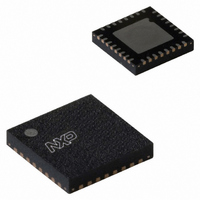
LPC1342FHN33,551 NXP Semiconductors, LPC1342FHN33,551 Datasheet - Page 22

LPC1342FHN33,551
Manufacturer Part Number
LPC1342FHN33,551
Description
IC MCU 32BIT 16KB FLASH 33HVQFN
Manufacturer
NXP Semiconductors
Series
LPC13xxr
Specifications of LPC1342FHN33,551
Program Memory Type
FLASH
Program Memory Size
16KB (16K x 8)
Package / Case
33-VQFN Exposed Pad, 33-HVQFN, 33-SQFN, 33-DHVQFN
Core Processor
ARM® Cortex-M3™
Core Size
32-Bit
Speed
72MHz
Connectivity
I²C, Microwire, SPI, SSI, SSP, UART/USART, USB
Peripherals
Brown-out Detect/Reset, POR, WDT
Number Of I /o
28
Ram Size
4K x 8
Voltage - Supply (vcc/vdd)
2 V ~ 3.6 V
Data Converters
A/D 8x10b
Oscillator Type
Internal
Operating Temperature
-40°C ~ 85°C
Processor Series
LPC13
Core
ARM Cortex M3
Data Bus Width
32 bit
Data Ram Size
4 KB
Interface Type
I2C, UART
Maximum Clock Frequency
72 MHz
Number Of Programmable I/os
28
Number Of Timers
4
Operating Supply Voltage
3.3 V
Maximum Operating Temperature
+ 85 C
Mounting Style
SMD/SMT
3rd Party Development Tools
MDK-ARM, RL-ARM, ULINK2
Minimum Operating Temperature
- 40 C
On-chip Adc
10 bit, 8 Channel
Package
33HVQFN EP
Device Core
ARM Cortex M3
Family Name
LPC1000
Maximum Speed
72 MHz
Lead Free Status / RoHS Status
Lead free / RoHS Compliant
For Use With
622-1005 - USB IN-CIRCUIT PROG ARM7 LPC2K
Eeprom Size
-
Lead Free Status / Rohs Status
Lead free / RoHS Compliant
Other names
568-4946
935289656551
935289656551
NXP Semiconductors
LPC1311_13_42_43
Product data sheet
7.16.1 Features
7.17.1 Integrated oscillators
7.15 System tick timer
7.16 Watchdog timer
7.17 Clocking and power control
The ARM Cortex-M3 includes a system tick timer (SYSTICK) that is intended to generate
a dedicated SYSTICK exception at a fixed time interval, normally set to 10 ms.
The purpose of the watchdog is to reset the microcontroller within a selectable time
period. When enabled, the watchdog will generate a system reset if the user program fails
to ‘feed’ (or reload) the watchdog within a predetermined amount of time.
The LPC1311/13/42/43 include three independent oscillators. These are the system
oscillator, the Internal RC oscillator (IRC), and the watchdog oscillator. Each oscillator can
be used for more than one purpose as required in a particular application.
•
•
•
•
•
•
•
•
•
•
Four match registers per timer that allow:
– Continuous operation with optional interrupt generation on match.
– Stop timer on match with optional interrupt generation.
– Reset timer on match with optional interrupt generation.
Up to four external outputs corresponding to match registers, with the following
capabilities:
– Set LOW on match.
– Set HIGH on match.
– Toggle on match.
– Do nothing on match.
Internally resets chip if not periodically reloaded.
Debug mode.
Enabled by software but requires a hardware reset or a watchdog reset/interrupt to be
disabled.
Incorrect/incomplete feed sequence causes reset/interrupt if enabled.
Flag to indicate watchdog reset.
Programmable 32-bit timer with internal prescaler.
Selectable time period from (T
multiples of T
The Watchdog Clock (WDCLK) source can be selected from the Internal RC oscillator
(IRC), the watchdog oscillator, or the main clock. This gives a wide range of potential
timing choices of watchdog operation under different power reduction conditions. It
also provides the ability to run the WDT from an entirely internal source that is not
dependent on an external crystal and its associated components and wiring for
increased reliability.
All information provided in this document is subject to legal disclaimers.
cy(WDCLK)
Rev. 3 — 10 August 2010
× 4.
cy(WDCLK)
× 256 × 4) to (T
32-bit ARM Cortex-M3 microcontroller
LPC1311/13/42/43
cy(WDCLK)
× 2
© NXP B.V. 2010. All rights reserved.
32
× 4) in
22 of 62


