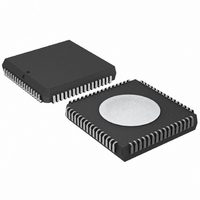
P87C554SBAA,512 NXP Semiconductors, P87C554SBAA,512 Datasheet - Page 13

P87C554SBAA,512
Manufacturer Part Number
P87C554SBAA,512
Description
IC 80C51 MCU 16K OTP 64-PLCC
Manufacturer
NXP Semiconductors
Series
87Cr
Specifications of P87C554SBAA,512
Core Processor
8051
Core Size
8-Bit
Speed
16MHz
Connectivity
EBI/EMI, I²C, UART/USART
Peripherals
POR, PWM, WDT
Number Of I /o
40
Program Memory Size
16KB (16K x 8)
Program Memory Type
OTP
Ram Size
512 x 8
Voltage - Supply (vcc/vdd)
2.7 V ~ 5.5 V
Data Converters
A/D 8x10b
Oscillator Type
Internal
Operating Temperature
0°C ~ 70°C
Package / Case
68-PLCC
Cpu Family
87C
Device Core
80C51
Device Core Size
8b
Frequency (max)
16MHz
Interface Type
I2C/UART
Total Internal Ram Size
512Byte
# I/os (max)
40
Number Of Timers - General Purpose
3
Operating Supply Voltage (typ)
5V
Operating Supply Voltage (max)
5.5V
Operating Supply Voltage (min)
4.5V
On-chip Adc
7-chx10-bit
Instruction Set Architecture
CISC
Operating Temp Range
0C to 70C
Operating Temperature Classification
Commercial
Mounting
Surface Mount
Pin Count
68
Package Type
PLCC
Processor Series
P87C5x
Core
80C51
Data Bus Width
8 bit
Data Ram Size
512 B
Maximum Clock Frequency
16 MHz
Number Of Programmable I/os
40
Number Of Timers
3
Operating Supply Voltage
2.7 V to 5.5 V
Maximum Operating Temperature
+ 70 C
Mounting Style
SMD/SMT
3rd Party Development Tools
PK51, CA51, A51, ULINK2
Minimum Operating Temperature
0 C
Lead Free Status / RoHS Status
Lead free / RoHS Compliant
Eeprom Size
-
Lead Free Status / Rohs Status
Compliant
Other names
568-1254-5
935263385512
P87C554SBAA
935263385512
P87C554SBAA
Available stocks
Company
Part Number
Manufacturer
Quantity
Price
Company:
Part Number:
P87C554SBAA,512
Manufacturer:
NXP Semiconductors
Quantity:
10 000
Philips Semiconductors
Dual DPTR
The dual DPTR structure (see Figure 6) is a way by which the chip
will specify the address of an external data memory location. There
are two 16-bit DPTR registers that address the external memory,
and a single bit called DPS = AUXR1/bit0 that allows the program
code to switch between them.
The DPS bit status should be saved by software when switching
between DPTR0 and DPTR1.
2002 Mar 25
80C51 8-bit microcontroller – 12 clock operation
16K/512 OTP/RAM, 8 channel 10-bit A/D, I
capture/compare, high I/O
AUXR1
BIT0
DPS
(83H)
DPH
FF
00
Figure 6.
Figure 5. Internal and External Data Memory Address Space with EXTRAM = 0
(82H)
DPL
256 BYTES
ERAM
DPTR1
DPTR0
FF
80
00
EXTERNAL
MEMORY
DATA
INTERNAL RAM
INTERNAL RAM
128 BYTES
128 BYTES
LOWER
UPPER
SU00745A
2
C, PWM,
11
FF
80
00
Note that bit 2 is not writable and is always read as a zero. This
allows the DPS bit to be quickly toggled simply by executing an
INC AUXR1 instruction without affecting the other bits.
DPTR Instructions
The instructions that refer to DPTR refer to the data pointer that is
currently selected using the AUXR1/bit 0 register. The six
instructions that use the DPTR are as follows:
The data pointer can be accessed on a byte-by-byte basis by
specifying the low or high byte in an instruction which accesses the
SFRs. See application note AN458 for more details.
INC DPTR
MOV DPTR, #data16
MOV A, @ A+DPTR
MOVX A, @ DPTR
MOVX @ DPTR , A
JMP @ A + DPTR
FUNCTION
REGISTER
SPECIAL
FFFF
0100
0000
Increments the data pointer by 1
Loads the DPTR with a 16-bit constant
Move code byte relative to DPTR to ACC
Move external RAM (16-bit address) to
ACC
Move ACC to external RAM (16-bit
address)
Jump indirect relative to DPTR
EXTERNAL
MEMORY
DATA
SU00980
P87C554
Product data


