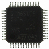
STM8S105C4T6 STMicroelectronics, STM8S105C4T6 Datasheet - Page 114

STM8S105C4T6
Manufacturer Part Number
STM8S105C4T6
Description
MCU 16KB FLASH MEM 16MHZ 48LQFP
Manufacturer
STMicroelectronics
Series
STM8Sr
Datasheet
1.STM8S105C4T6.pdf
(127 pages)
Specifications of STM8S105C4T6
Core Processor
STM8
Core Size
8-Bit
Speed
16MHz
Connectivity
I²C, IrDA, LIN, SPI, UART/USART
Peripherals
Brown-out Detect/Reset, POR, PWM, WDT
Number Of I /o
38
Program Memory Size
16KB (16K x 8)
Program Memory Type
FLASH
Eeprom Size
1K x 8
Ram Size
2K x 8
Voltage - Supply (vcc/vdd)
2.95 V ~ 5.5 V
Data Converters
A/D 10x10b
Oscillator Type
Internal
Operating Temperature
-40°C ~ 85°C
Package / Case
48-LQFP
Processor Series
STM8S10x
Core
STM8
Data Bus Width
8 bit
Data Ram Size
2 KB
Interface Type
I2C, SPI, UART
Maximum Clock Frequency
16 MHz
Number Of Programmable I/os
38
Number Of Timers
9
Maximum Operating Temperature
+ 85 C
Mounting Style
SMD/SMT
3rd Party Development Tools
EWSTM8
Development Tools By Supplier
STICE-SYS001
Minimum Operating Temperature
- 40 C
On-chip Adc
10 bit, 10 Channel
For Use With
497-10040 - EVAL KIT STM8S DISCOVERY497-10593 - KIT STARTER FOR STM8S207/8 SER497-5046 - KIT TOOL FOR ST7/UPSD/STR7 MCU
Lead Free Status / RoHS Status
Lead free / RoHS Compliant
Other names
497-8818
Available stocks
Company
Part Number
Manufacturer
Quantity
Price
Company:
Part Number:
STM8S105C4T6
Manufacturer:
MICRONAS
Quantity:
2 100
Company:
Part Number:
STM8S105C4T6
Manufacturer:
STMicroelectronics
Quantity:
10 000
Part Number:
STM8S105C4T6
Manufacturer:
ST
Quantity:
20 000
Company:
Part Number:
STM8S105C4T6TR
Manufacturer:
STMicroelectronics
Quantity:
10 000
Part Number:
STM8S105C4T6TR
Manufacturer:
ST
Quantity:
20 000
Thermal characteristics
12
12.1
114/127
Thermal characteristics
The maximum chip junction temperature (T
Operating conditions
The maximum chip-junction temperature, T
the following equation:
T
Where:
•
•
•
•
•
1. Thermal resistances are based on JEDEC JESD51-2 with 4-layer PCB in a natural
Reference document
JESD51-2 integrated circuits thermal test method environment conditions - natural convection
(still air). Available from www.jedec.org.
Symbol
Θ
Θ
Θ
Θ
Jmax
JA
JA
JA
JA
T
Θ
P
P
power.
P
+ Σ((V
and high level in the application.
convection environment.
Amax
I/Omax
Dmax
INTmax
JA
= T
is the package junction-to-ambient thermal resistance in ° C/W
Amax
is the maximum ambient temperature in °C
DD
is the sum of P
represents the maximum power dissipation on output pinsWhere:P
is the product of I
-V
OH)
+ (P
Parameter
Thermal resistance junction-ambient
LQFP 48 - 7 x 7 mm
Thermal resistance junction-ambient
LQFP 44 - 10 x 10 mm
Thermal resistance junction-ambient
LQFP 32 - 7 x 7 mm
Thermal resistance junction-ambient
VQFPN 32 - 5 x 5 mm
*I
Dmax
OH
), taking into account the actual V
x Θ
INTmax
Table 58: Thermal characteristics
JA
DD
)
DocID14771 Rev 10
andV
and P
DD
I/Omax
, expressed in Watts. This is the maximum chip internal
Jmax
J max
(P
Dmax
, in degrees Celsius, may be calculated using
) must never exceed the values given in
= P
INTmax
OL
/I
OL and
+ P
(1)
I/Omax
V
Value
57
54
60
22
OH
/I
)
OH
of the I/Os at low
I/Omax
STM8S105xx
=Σ (V
Unit
°C/W
°C/W
°C/W
°C/W
OL
*I
OL
)


