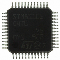
STM8S105C4T6 STMicroelectronics, STM8S105C4T6 Datasheet - Page 18

STM8S105C4T6
Manufacturer Part Number
STM8S105C4T6
Description
MCU 16KB FLASH MEM 16MHZ 48LQFP
Manufacturer
STMicroelectronics
Series
STM8Sr
Datasheet
1.STM8S105C4T6.pdf
(127 pages)
Specifications of STM8S105C4T6
Core Processor
STM8
Core Size
8-Bit
Speed
16MHz
Connectivity
I²C, IrDA, LIN, SPI, UART/USART
Peripherals
Brown-out Detect/Reset, POR, PWM, WDT
Number Of I /o
38
Program Memory Size
16KB (16K x 8)
Program Memory Type
FLASH
Eeprom Size
1K x 8
Ram Size
2K x 8
Voltage - Supply (vcc/vdd)
2.95 V ~ 5.5 V
Data Converters
A/D 10x10b
Oscillator Type
Internal
Operating Temperature
-40°C ~ 85°C
Package / Case
48-LQFP
Processor Series
STM8S10x
Core
STM8
Data Bus Width
8 bit
Data Ram Size
2 KB
Interface Type
I2C, SPI, UART
Maximum Clock Frequency
16 MHz
Number Of Programmable I/os
38
Number Of Timers
9
Maximum Operating Temperature
+ 85 C
Mounting Style
SMD/SMT
3rd Party Development Tools
EWSTM8
Development Tools By Supplier
STICE-SYS001
Minimum Operating Temperature
- 40 C
On-chip Adc
10 bit, 10 Channel
For Use With
497-10040 - EVAL KIT STM8S DISCOVERY497-10593 - KIT STARTER FOR STM8S207/8 SER497-5046 - KIT TOOL FOR ST7/UPSD/STR7 MCU
Lead Free Status / RoHS Status
Lead free / RoHS Compliant
Other names
497-8818
Available stocks
Company
Part Number
Manufacturer
Quantity
Price
Company:
Part Number:
STM8S105C4T6
Manufacturer:
MICRONAS
Quantity:
2 100
Company:
Part Number:
STM8S105C4T6
Manufacturer:
STMicroelectronics
Quantity:
10 000
Part Number:
STM8S105C4T6
Manufacturer:
ST
Quantity:
20 000
Company:
Part Number:
STM8S105C4T6TR
Manufacturer:
STMicroelectronics
Quantity:
10 000
Part Number:
STM8S105C4T6TR
Manufacturer:
ST
Quantity:
20 000
Product overview
4.13
4.14
4.14.1
18/127
Timer
TIM4
Counter
size
(bits)
8
Analog-to-digital converter (ADC1)
The STM8S105xx products contain a 10-bit successive approximation A/D converter (ADC1)
with up to 10 multiplexed input channels and the following main features:
•
•
•
•
•
•
•
•
•
•
Communication interfaces
The following communication interfaces are implemented:
•
•
•
UART2
Main features
•
•
•
•
•
Input voltage range: 0 to V
Conversion time: 14 clock cycles
Single and continuous and buffered continuous conversion modes
Buffer size (n x 10 bits) where n = number of input channels
Scan mode for single and continuous conversion of a sequence of channels
Analog watchdog capability with programmable upper and lower thresholds
Analog watchdog interrupt
External trigger input
Trigger from TIM1 TRGO
End of conversion (EOC) interrupt
UART2: Full feature UART, synchronous mode, SPI master mode, Smartcard mode, IrDA
mode, LIN2.1 master/slave capability
SPI : Full and half-duplex, 8 Mbit/s
I²C: Up to 400 Kbit/s
One Mbit/s full duplex SCI
SPI emulation
High precision baud rate generator
Smartcard emulation
IrDA SIR encoder decoder
Note: Additional AIN12 analog input is not selectable in ADC scan mode or with analog
watchdog. Values converted from AIN12 are stored only into the ADC_DRH/ADC_DRL
registers.
Prescaler
Any power of 2 from
1 to 128
Counting
mode
Up
DDA
DocID14771 Rev 10
CAPCOM
channels
0
Complem.
outputs
0
Ext.
trigger
No
Timer
synchronization/
chaining
STM8S105xx


